
Solar cover plate glass

A cover glass and solar energy technology, which is applied in photovoltaic power generation, electrical components, circuits, etc., can solve the problems of not being able to effectively improve the transmittance, increase the reflectivity, and reduce the glass transmittance, so as to improve the overall light transmittance Ratio, reduce the reflection angle, reduce the effect of reflectivity

Inactive Publication Date: 2015-08-05
CSG HOLDING +1
View PDF6 Cites 5 Cited by
  • Summary
  • Abstract
  • Description
  • Claims
  • Application Information

AI Technical Summary

Problems solved by technology

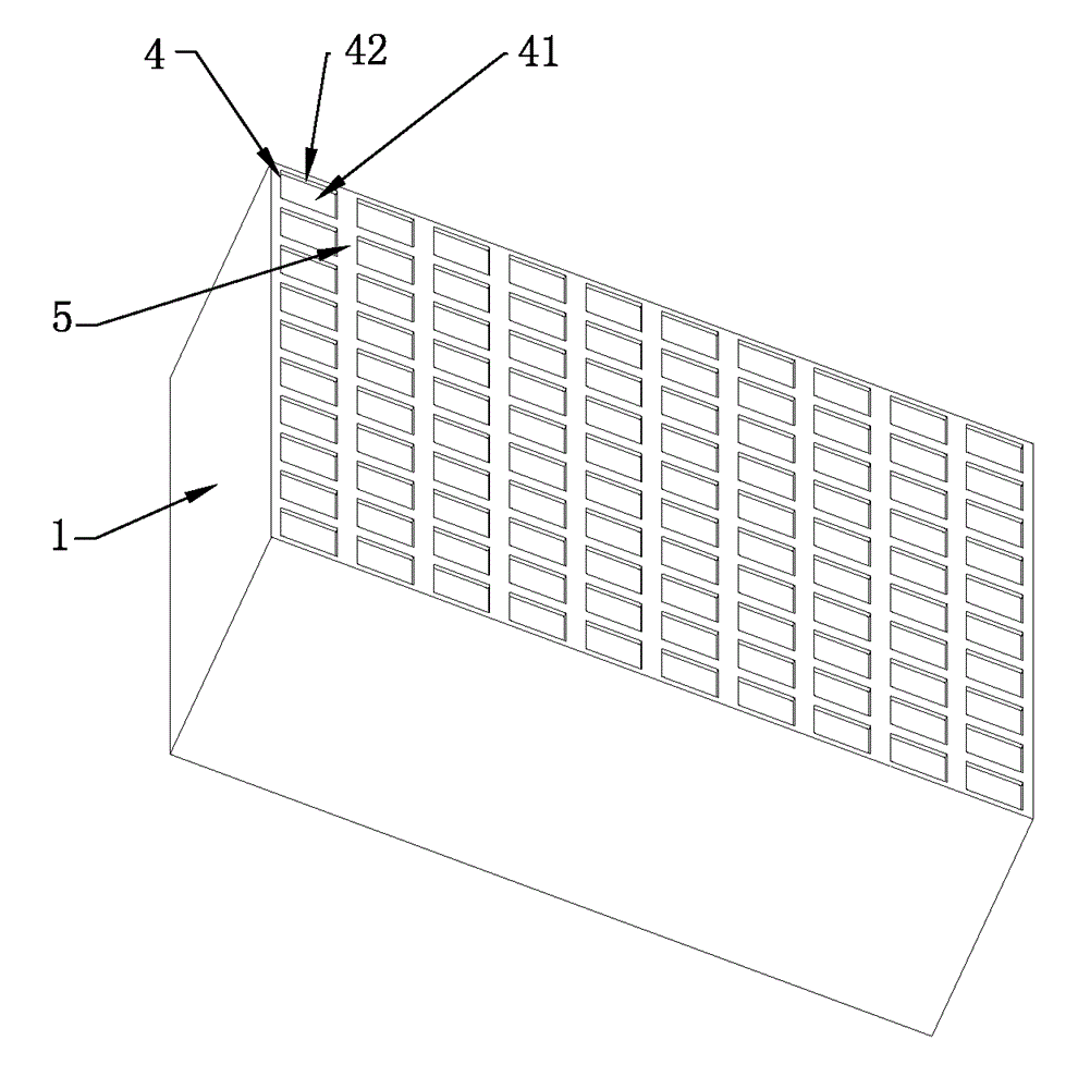
At present, due to technical habits, the groove is generally completely formed into a smooth concave surface structure. Although this structure is relatively easy to realize in technology, the inventor also found that the seriousness of this structure exists in practical applications. Disadvantages: When the light exits from the glass toward the bottom of the glass, the bottom of the glass and the groove bottom of the groove serve as the exit interface, and the light will form a certain reflection at the exit interface, and the groove structure will lead to a further increase in reflectivity, and then leading to a decrease in the transmittance of the glass
[0004] In this regard, Chinese patent CN201084736Y discloses an ultra-white solar panel with a new type of pattern, which attempts to improve the structure of the pattern so that the light can emit secondary and tertiary refraction to improve the transmittance. However, this idea is still based on The groove bottom is a curved surface design idea. After improvement, although it can improve the transmittance of some obliquely incident light rays into the glass, most of the light rays of the cover glass are still directly incident in practical applications. For direct incident light, this flower structure is still not enough to effectively improve the transmittance

Method used


Image

  • Solar cover plate glass
  • Solar cover plate glass
  • Solar cover plate glass

Examples


Embodiment

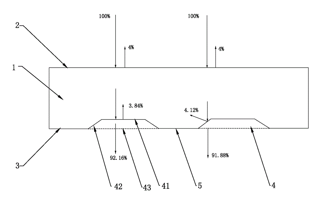
[0042] The third specific embodiment of a solar cover glass created by the present invention, the main technical solution of this embodiment is the same as that of embodiment 2, and the features not explained in this embodiment shall be explained in embodiment 2, here No further details will be given. The difference between this embodiment and embodiment 2 is that, as Figure 4 As shown, the section is a curved surface of an arc, and the inclination angle α between the secant of the section of the groove wall 42 and the bottom surface 3 of the panel body 1 is greater than 120°.

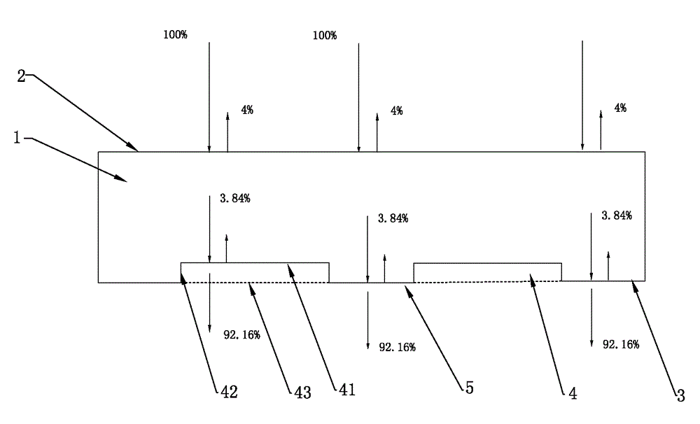
[0043] For this embodiment, when the light is vertically incident on the cover glass, part of the light will be reflected on the upper surface of the cover glass, the reflected part is about 4%, and the remaining 96% enters the cover glass. The glass propagates vertically downward, part of which reaches the bottom surface 3 of the cover glass, part of which reaches the bottom 41 of the groove 4, and ...


PUM


Abstract

The invention relates to the technical field of cover plate glass, and especially relates to solar cover plate glass. The bottom surface of a panel is provided with a groove. What is different from prior arts is that the bottom of the groove is arranged to be a plane parallel to the bottom surface of a panel body, and the area of the plane is not smaller than 50% of the area of a notch (i.e., the area of the groove bottom, which is composed of the plane, of the groove is not smaller than 50% of the projection area of the groove in a horizontal plane). Therefore, the cover plate glass provided by the invention can effectively reduce reflection angles of a majority of light in an emission interface, accordingly reduces the reflectivity of the light in the emission interface of the cover plate glass and effectively improves the integral light transmittance of the cover plate glass.

Description

technical field [0001] The invention relates to the technical field of cover glass, in particular to a solar cover glass. Background technique [0002] In solar photovoltaic panels, it is generally necessary to use transparent cover glass as the front panel, and place the photovoltaic element on the bottom of the transparent glass to protect the photovoltaic element. Therefore, it is generally required that as much light as possible must pass through the cover glass to reach the photovoltaic element. [0003] On the other hand, the existing cover glass needs to be provided with some grooves on its bottom surface, so that the photovoltaic element and the cover glass can be better fixed together. At present, due to technical habits, the groove is generally completely formed into a smooth concave surface structure. Although this structure is relatively easy to realize in technology, the inventor also found that the seriousness of this structure exists in practical applications...

Claims


Application Information

Patent Timeline
Patent Type & Authority Applications(China)
IPC IPC(8): H01L31/0236H01L31/048
CPCY02E10/50H01L31/0236H01L31/048
Inventor 常江叶金林刘燕娟何进刘明刚武林雨
Owner CSG HOLDING
Learn More