Method for calculating camera field angle

A camera and field of view technology, applied in the field of radio, television and film equipment, can solve problems such as the inability to apply zoom lenses, calculate the camera field of view, and the inaccuracy of the rangefinder to follow the target, etc., to achieve the effect of simple operation

Active Publication Date: 2015-08-05
MOVCAM TECH
View PDF4 Cites 21 Cited by
  • Summary
  • Abstract
  • Description
  • Claims
  • Application Information

AI Technical Summary

Problems solved by technology

[0002] In the existing technology, there are devices that use ranging sensors and video target tracking to perform automatic focusing, but manual calibration of the camera's field of view is required, and the camera's field of view cannot be calculated using the focal length of the lens, so it cannot be applied to zoom lenses , causing the rangefinder to follow the target inaccurately
Generally sp

Method used


Image

  • Method for calculating camera field angle

Examples


Embodiment Construction

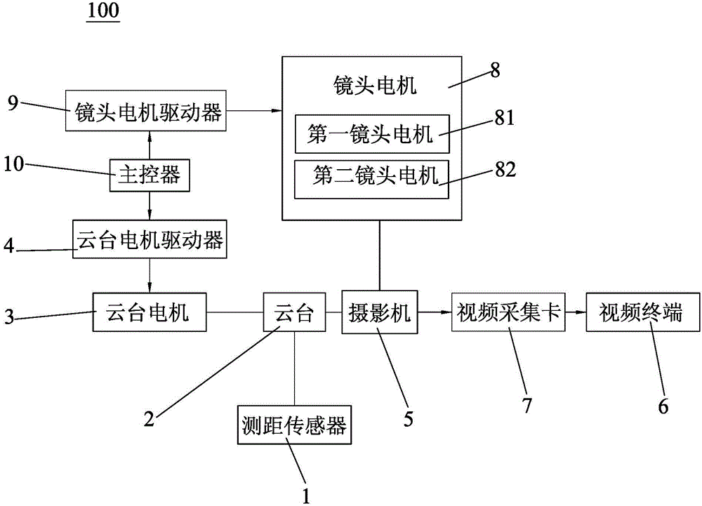
[0025] The embodiments of the present invention will now be described with reference to the accompanying drawings, in which similar element numbers represent similar elements. As mentioned above, such as figure 1 As shown, the method for calculating the angle of view of a camera provided by the present invention, the automatic follow-focus device 100 based on video target tracking, includes: (1) turning on the red dot laser transmitter; (2) manually controlling the lens zoom ring to rotate to a certain angle , At the same time, control the rotation of the pan / tilt motor 4 to make the red dot laser emitter point to the edge of the camera 5 field of view, and save the current lens zoom circle rotation angle and the camera 5 field of view angle at the same time, repeat the above process many times to record multiple sets of lens zoom circles Correspondence between the rotation angle and the 5 field angles of the camera.

[0026] By knowing the correspondence between the rotation an...


PUM


Abstract

The invention discloses a method for calculating a camera field angle, which is based on an automatic follow focus device for video target tracking. The method comprises a first step of booting a red dot laser transmitter; and a second step of controlling a lens zooming ring to rotate to a certain angle by a hand, in the meantime, controlling a cloud holder motor to rotate, so as to enable the red dot laser transmitter to point to the edge of a camera field, storing the rotation angle of the current lens zooming ring and the camera field angle simultaneously, repeating the above process more than once, and recording the correspondences of the rotation angles of multiple lens zooming rings and the camera field angle. According to the method, the current field angle of the camera is calculated through detection of the focal distance of the zooming lens, and the method can automatically calculate the camera field angle according to the change of the lens focal distance and is simple to operate.

Description

Technical field [0001] The invention relates to the field of radio, television and film equipment, in particular to a method for calculating the angle of view of a camera. Background technique [0002] In the existing technology, there are devices that use range finding sensors and video target tracking for auto-focusing, but the camera's field of view angle needs to be manually calibrated, and the camera's field of view angle cannot be calculated by the lens focal length, so it cannot be applied to zoom lenses , Causing the rangefinder to follow the target not accurately. Generally speaking, the installation position of the gimbal and the optical axis of the camera have a certain positional deviation in the horizontal or vertical direction. The existing automatic focus tracking based on video target tracking cannot automatically correct the level according to the vertical distance between the target and the focal plane. Or vertical position deviation. [0003] Therefore, there i...

Claims


Application Information

Patent Timeline
IPC IPC(8): H04N5/232
Inventor 徐红兵何景川
Owner MOVCAM TECH
Why Eureka
Try Eureka