Supercharge Your Innovation With Domain-Expert AI Agents!

Lightwave inspection diagnosis device

A technology of inspection and diagnosis and light wave, which is applied in the field of medical equipment, can solve the problems of diagnosis and treatment analysis errors, waste of time and energy of medical staff, and increase the difficulty of medical staff's work, so as to achieve the effect of convenient use, complete functions, and ease of work difficulty

Inactive Publication Date: 2015-08-12
董瑞兰
View PDF9 Cites 2 Cited by
  • Summary
  • Abstract
  • Description
  • Claims
  • Application Information

AI Technical Summary

Problems solved by technology

[0002] Medical personnel need to use a variety of inspection, diagnosis and analysis devices for inspection, diagnosis and treatment when performing detection, diagnosis and treatment of disease patients. In the past, medical personnel needed to use various inspection, diagnosis and analysis devices to cooperate with each other when performing detection, diagnosis and treatment to complete the diagnosis and treatment together. Different instruments have very different requirements for medical staff, and switching treatment instruments back and forth is likely to cause errors in diagnosis and treatment analysis, affecting the diagnosis and treatment of diseases, and the previous inspection and diagnosis analysis devices cannot intelligently analyze and process the test results, which requires a lot of waste of medical staff. It takes time and energy to organize and process, making the detection, diagnosis and treatment process cumbersome and complicated. If things go on like this, it will greatly increase the difficulty of the work of medical staff

Method used


Image

  • Lightwave inspection diagnosis device
  • Lightwave inspection diagnosis device
  • Lightwave inspection diagnosis device

Examples


Embodiment Construction

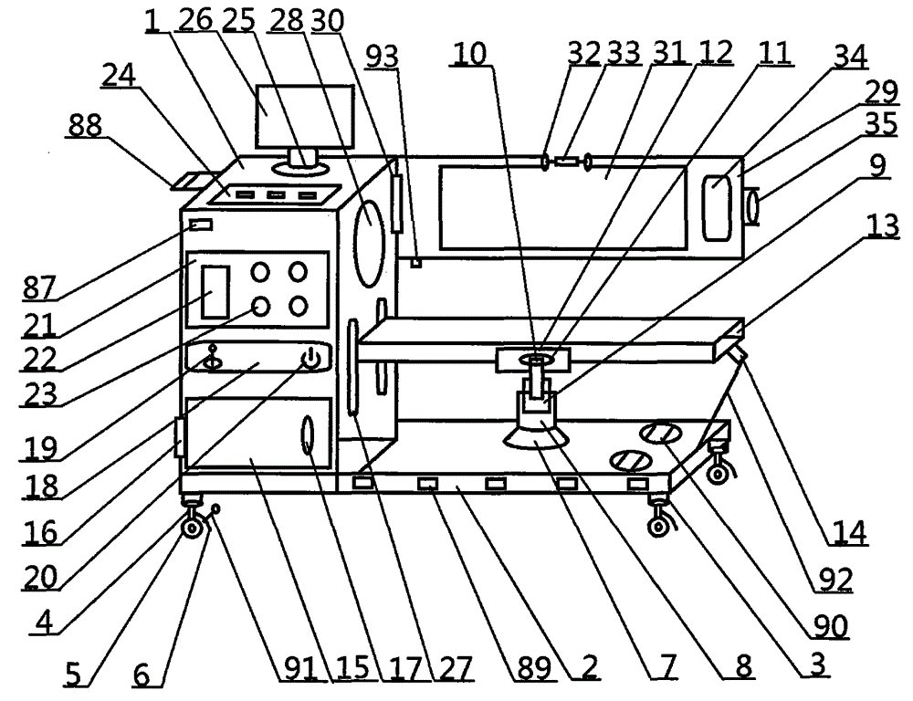
[0022] The light wave inspection and diagnosis device of the present invention will be described in detail below with reference to the accompanying drawings.

[0023] Such as figure 1 As shown, the light wave inspection and diagnosis device of the present invention includes a main body 1, an equipment carrying platform 2 is arranged on the lower side of the main body 1, a supporting leg 3 is arranged on the lower side of the equipment supporting platform 2, and a shock absorbing rod 4 is arranged on the lower side of the supporting leg 3 The lower side of the damping rod 4 is provided with a moving roller 5, the right side of the damping rod 4 is provided with an anti-wear baffle 6, the upper side of the equipment carrying platform 2 is provided with a lifting round table 7, and the upper side of the lifting round table 7 is provided with a cashier 8, The upper side of the cashier warehouse 8 is provided with a booster tube 9, and the upper side of the booster tube 9 is provid...


PUM


Abstract

The invention relates to a lightwave inspection diagnosis device, belonging to the technical field of medical apparatus and instruments. The lightwave inspection diagnosis device provided by the invention comprises a main body, wherein a ray inspection transmitting tube is arranged inside the main body, an emergency storage battery is arranged at the lower side of the ray inspection transmitting tube, an inspection ray generation box is arranged inside the ray inspection transmitting tube, a light control hole is formed in the upper side of the inspection ray generation box, a ventilation plate is arranged at the rear side of an inspection sound wave generation box, a gas exchange opening is formed in the rear side of the ventilation plate, a fixing circular ring is connected with the inspection sound wave generation box through a supporting link, and a terminal inspection wave outlet is formed in the right side of an inspection wave emitting strip. The lightwave inspection diagnosis device is complete in function and convenient in use and is timesaving, laborsaving, scientific, convenient, safe and efficient, intelligent and accurate during the diagnosis and treatment of disease patients, and thus, the difficulty of work of medical personnel is reduced.

Description

technical field [0001] The invention belongs to the technical field of medical devices, and in particular relates to a light wave inspection and diagnosis device. Background technique [0002] Medical personnel need to use a variety of inspection, diagnosis and analysis devices for inspection, diagnosis and treatment when performing detection, diagnosis and treatment of disease patients. In the past, medical personnel needed to use various inspection, diagnosis and analysis devices to cooperate with each other when performing detection, diagnosis and treatment to complete the diagnosis and treatment together. Different instruments have very different requirements for medical staff, and switching treatment instruments back and forth is likely to cause errors in diagnosis and treatment analysis, affecting the diagnosis and treatment of diseases, and the previous inspection and diagnosis analysis devices cannot intelligently analyze and process the test results, which requires a...

Claims


Application Information

Patent Timeline
Patent Type & Authority Applications(China)
IPC IPC(8): A61B5/00A61B8/00
Inventor 董瑞兰汪桂霞
Owner 董瑞兰
Features
  • R&D
  • Intellectual Property
  • Life Sciences
  • Materials
  • Tech Scout
  • Unparalleled Data Quality
  • Higher Quality Content
  • 60% Fewer Hallucinations
Learn More