Material evenly distributing device of flow stabilizing cylinder of central transmission thickener

A technology of uniform material distribution and central transmission, which is applied to the feeding/discharging device of the settling tank, etc., can solve the problems of reducing the service life of rake racks, increasing production costs, and uneven torque, so as to improve processing capacity and prolong service life , the effect of increased processing capacity

Inactive Publication Date: 2015-08-12
HUAIBEI ZHONGFEN MINING MACHINERY
View PDF4 Cites 9 Cited by
  • Summary
  • Abstract
  • Description
  • Claims
  • Application Information

AI Technical Summary

Problems solved by technology

[0003] In order to reduce the kinetic energy of the material entering the concentration tank from the feeding pipe and improve the settling effect of the material, the central drive thickener sometimes installs a steady flow cylinder on the drum of the thickener, such as the patent No. 201010590537. The steady flow device described in the invention patent, that is, the radial diversion guide plate, flow guide plate, outer flow guide cylinder and inner flow guide cylinder in the flow stabilization cylinder, will reduce the kinetic energy of the material entering the concentration tank to a certain extent. , so as to effectively improve the working efficiency of the central drive concentrator. However, although the material entering the steady flow cylinder through the feed pipe is restricted to settle down in the steady flow cylinder, the inlet of the feed pipe is fixed in the steady flow cylinder. One side, so the material entering the steady flow cylinder from the feeding pipe cannot completely achieve uniform distribution and settlement inside the steady flow cylinder. The settlement on one side of the nozzle will inevitably lead to the following phenomena: on the one hand, when the material enters the steady flow cylinder and is close to the side of the feeding nozzle, more coarse particles will settle, that is to say, the bottom of the tumbler is located at the feeding pipe. There are more coarse-grained materials on one side of the mouth, but there are less or no coarse-grained materials on the other parts of the bottom of the tumbler on the side of the feed pipe mouth, which will cause the rake frame to receive uneven torque when it rotates along the tumbler. Accidents such as lifting the rake, damaging the reducer or even destroying the rake frame will greatly reduce the service life of the rake frame, resulting in an increase in the production cost of the enterprise and time-consuming and laborious; The kinetic energy of the material in the steady flow cylinder, the material flowing from the steady flow cylinder into the concentration tank still has kinetic energy, which is not conducive to the settlement of fine particles in the material, so that the production capacity per unit area of ​​the concentration tank is reduced and the settlement area of ​​the concentration tank needs to be increased. This will inevitably lead to an increase in the construction cost of the concentrator; in addition, in severe cases, you can see outwardly spreading waves on the liquid surface of the concentrator, and such material kinetic energy can even re-stir the settled materials in the concentrator. Greatly reduce the production efficiency of the thickener

Method used


Image

  • Material evenly distributing device of flow stabilizing cylinder of central transmission thickener
  • Material evenly distributing device of flow stabilizing cylinder of central transmission thickener
  • Material evenly distributing device of flow stabilizing cylinder of central transmission thickener

Examples


Embodiment 1

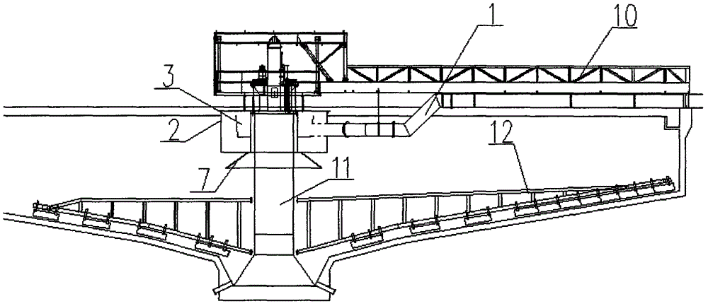
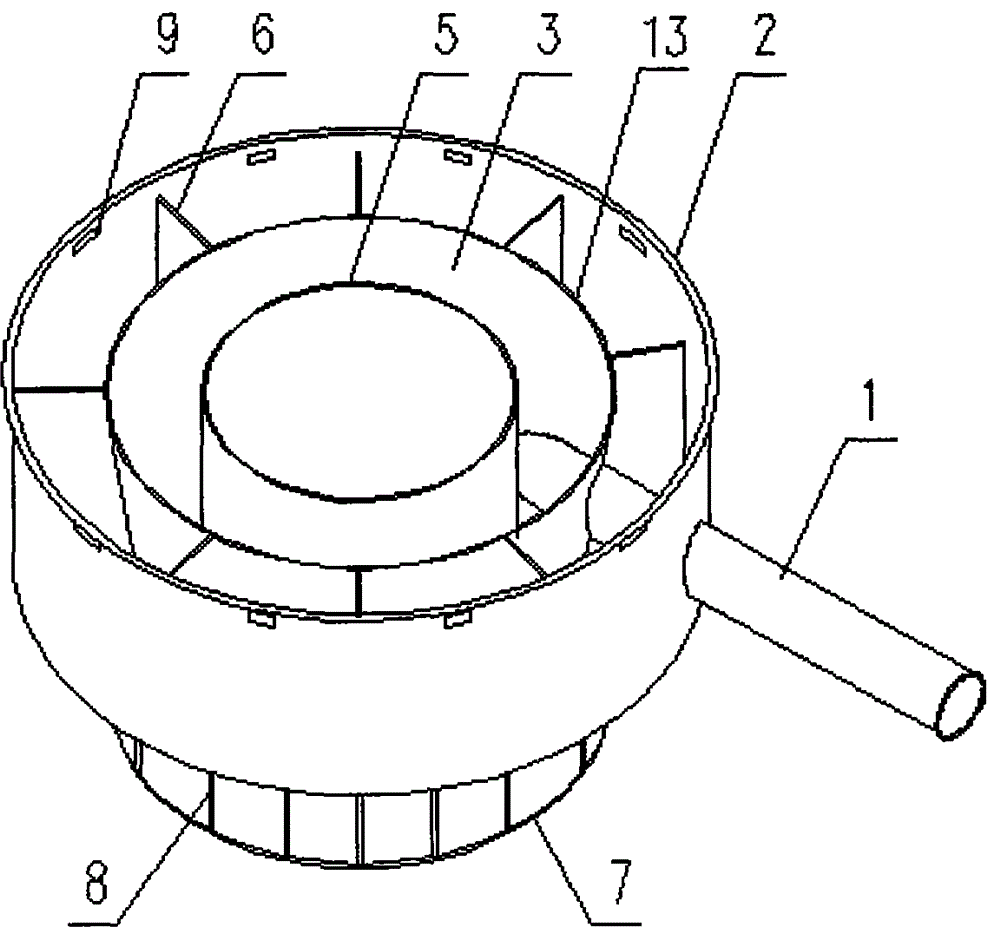
[0018] Example as figure 1 As shown, the central drive concentrator includes a feed pipe 1 , a bridge frame 10 , a rotating cage 11 and a rake frame 12 . Such as figure 1 and figure 2 As shown, the flow stabilizing cylinder includes an outer guiding cylinder 2 , an inner guiding cylinder 7 and a connecting plate 8 , and the upper end of the outer guiding cylinder 2 is equidistantly provided with dilution ports 9 .

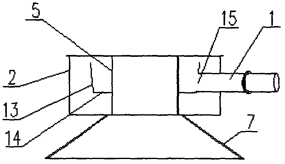
[0019] Such as figure 2 , image 3 and Figure 4 As shown, a uniform distribution device is arranged in the outer guide tube 2, and the uniform distribution device includes a distribution tank 3 and 8 fixing plates 6, and a dilution port 9 is provided at the upper end of the outer guide tube 2 between adjacent fixing plates 6. The cloth trough 3 comprises a cloth inner cylinder 5, a cloth outer cylinder 13 and a cloth bottom plate 14, and the cloth outer cylinder 13 and the cloth inner cylinder 5 are fixedly connected through the cloth bottom plate 14 to for...

Embodiment 2

[0023] Example two such as Figure 5 As shown, a cloth control board 4 is fixedly connected between the cloth outer cylinder 13 above the feed nozzle 15 and the cloth inner cylinder 5. The cloth control board 4 is arc-shaped, and the width of the cloth control board 4 is equal to the cloth outer cylinder 13 and the cloth inner cylinder 5. The distance between the cloth inner cylinder 5, the radian of the cloth control board 4 is 90°, that is, the length of the cloth control board 4 is equal to 1 / 4 of the circumference formed by the cloth outer cylinder 13 and the cloth inner cylinder 5, other settings and embodiments together. The material distribution control plate 4 can effectively prevent the slurry flowing out from the discharge nozzle 15 from directly overflowing to the top of the material outer tube 13 and enter the inner side of the outer guide tube 2, so as to prevent the material in the flow stabilization tube from being biased toward the rotating cage 11 located at t...


PUM

PropertyMeasurementUnit
angleaaaaaaaaaa

Abstract

The invention discloses a material evenly distributing device of flow stabilizing cylinder of central transmission thickener, relates to the field of additional devices of central transmission thickener, and aims to solve the problem that the material settlement is non-uniform in the conventional thickeners. The material evenly distributing device comprises a material distributing tank and a plurality of fixed plate; the material distributing tank comprises a material distributing inner cylinder, a material distributing outer cylinder, and a material distributing bottom plate; the material distributing inner cylinder and the material distributing outer cylinder are connected through the material distributing bottom plate to form a circular groove; a material feeding pipe goes through an external flow guiding cylinder, and the opening of the material feeding pipe is fixed in the inner side of the material distributing outer cylinder. The provided material evenly distributing device can make materials evenly settle around the periphery of the material distributing tank, reduces the interference on the inner water and bed of thickening tank, and effectively improves the processing performance of a thickener.

Description

technical field [0001] The invention relates to an additional device of a central drive concentrator, in particular to a uniform material distribution device of a steady flow cylinder of a central drive concentrator. Background technique [0002] At present, when the central drive thickener used by people is working normally, the slurry enters the thickening tank through the feeding pipe and spreads to the surroundings of the thickening tank. During this process, the material gradually sinks to the bottom of the inclined tank by its own gravity. At the same time, the motor drives the rollers to rotate around the center along the circular platform on the top of the thickening tank and drive the rotating cage and the rake frame to rotate together. The angled rake teeth on the rake frame move the materials settled at the bottom of the pool to the pool during the rotation process. Scraping to realize the concentration of materials, and the clarified water flows from the upper ov...

Claims


Application Information

Patent Timeline
Patent Type & Authority Applications(China)
IPC IPC(8): B01D21/24
Inventor 周杰
Owner HUAIBEI ZHONGFEN MINING MACHINERY
Why Eureka
Try Eureka