Eureka AIR delivers breakthrough ideas for toughest innovation challenges, trusted by R&D personnel around the world.

Material suction and discharge crushing fan

A material crushing and material technology, which is applied in the field of material suction, discharge and crushing fans, can solve the problems of inability to meet the needs of use, narrow use range, crushing processing, etc., and achieve the effect of saving raw materials, using multiple functions, and simple mechanical equipment.

Active Publication Date: 2018-05-08
林钧浩
View PDF8 Cites 0 Cited by
  • Summary
  • Abstract
  • Description
  • Claims
  • Application Information

AI Technical Summary

Problems solved by technology

[0002] Although the various material suction and discharge backflow fans and synchronous backflow fans used by people can directly suck and discharge various solid materials, they cannot be directly used for solid materials with large volume and area, and for solid materials that are easy to hang and entangle. Suction and discharge: For materials that need to be crushed, they cannot be directly crushed, but can only simply suck and discharge solid materials to be crushed, and can only simply suck and discharge solid materials that have been crushed and processed by other crushing machines, resulting in various suction and discharge materials. Both the fan and the synchronous backflow fan have certain limitations, the use range is narrow, the functions are few, and the uses are few, and they cannot meet the needs of people's multi-faceted use at the same time.

Method used


Image

  • Material suction and discharge crushing fan
  • Material suction and discharge crushing fan
  • Material suction and discharge crushing fan

Examples


Embodiment 1

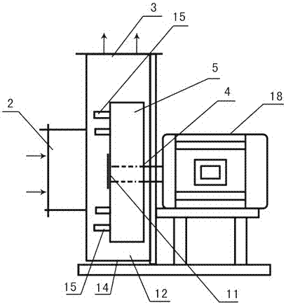
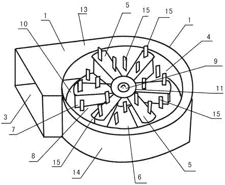
[0050] Embodiment 1, reference figure 1 , figure 2 , The material suction and discharge crushing fan includes a casing 1, a casing air inlet 2, and a casing air outlet 3. The casing is provided with a synchronous backflow fan impeller 4, and the impeller 4 is provided with impeller blades 5, and a reinforcing disk 11 in the middle of the impeller. Impeller air outlet 6, blade air outlet 7, impeller inner flow channel 8, impeller shaft sleeve 9, impeller blade disc 10, casing inner flow channel 12, impeller blade 5 (blade synchronous deflector is provided on the blade) and blade synchronization Blade-type material crushing teeth 15 are provided on the deflector, blade-type material crushing teeth 15 are provided on the impeller blade disc 10 in the inner flow channel 8 of the impeller, and a motor 18 is provided at the rear of the body, and the shaft of the motor 18 passes through the impeller shaft sleeve 9 is connected with impeller 4.

[0051] This example is used for the...

Embodiment 2

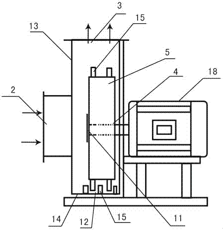
[0055] Embodiment 2, refer to image 3 , Figure 4 , this example is basically the same as Example 1, the difference is that there are no material crushing teeth on the axial side of the impeller blades in this example, but a blade type material is set on the casing radial side wall 14 of the casing inner flow channel 12 The crushing teeth 15 are provided with blade-type material crushing teeth 15 on the edge of the impeller blade disk 10 of the impeller air outlet 6, and the blade-type material crushing teeth 15 are set on the blade air outlet 7. This example is used for suction and discharge of broken, soft and fragile materials, such as plastic foam, melons and fruits, leaves, vegetable leaves, etc.

[0056] When working, the high-speed flowing soft and fragile materials discharged by the impeller in the inner flow channel of the casing collide with the material crushing teeth 15 rotating at high speed at the blade air outlet 7 and the edge of the impeller blade disc 10, a...

Embodiment 3

[0059] Embodiment 3, refer to Figure 5 , Image 6 , this example is the same as Example 1, the difference is that there is no material crushing tooth on the axial side wall of the impeller blade in this example, and a cylindrical material crushing tooth connecting piece 16 is set on the middle reinforcement plate 11 of the impeller in this example, and the cylindrical material The crushing tooth connecting piece 16 protrudes along the axial direction and extends into the air inlet 2 of the casing. The material crushing tooth connecting piece 16 is surrounded by a three-edged knife-type material crushing tooth 15 fixed on the material crushing tooth connecting piece, and the middle reinforcement plate of the impeller 11 forms an indirect connection structure with the material crushing teeth 15, and the reinforcement disc 11 in the middle of the impeller drives the material crushing teeth 15 to rotate at high speed. Material crushing teeth 15 are arranged on the inner wall of ...


PUM


Abstract

The utility model discloses a crushing fan for the suction and the discharge of materials, which comprises a casing, a casing air inlet, a casing air outlet, an impeller, an impeller blade, an impeller air outlet, a blade air outlet, an impeller inner flow channel, an impeller shaft sleeve, an impeller blade disc, an impeller intermediate reinforced plate, a casing inner flow channel, a casing axial sidewall, and a casing radial sidewall. The crushing fan is characterized in that the impeller inside the fan is provided with material crushing teeth. The material crushing teeth are connected with the through-flow part of the impeller. Compared with existing various special material crushing machinery, the above crushing fan is simple in mechanical equipment, raw-material-saving to machine and manufacture, convenient to convey, install and use, manpower-saving, material-saving, financial resource-saving, multiple in usage purpose and wide in application range. By means of the crushing fan, various crude blocks, particles and powdery finished product materials of different thickness requirements can be machined. When the crushing fan is used for crushing, machining and conveying materials, the crushing fan is good in effect, high in efficiency and saving-energy.

Description

technical field [0001] The invention relates to a material suction and discharge crushing fan, which belongs to the technical field of gas machinery. Background technique [0002] Although the various material suction and discharge backflow fans and synchronous backflow fans used by people can directly suck and discharge various solid materials, they cannot be directly used for solid materials with large volume and area, and for solid materials that are easy to hang and entangle. Suction and discharge: For materials that need to be crushed, they cannot be directly crushed, but can only simply suck and discharge solid materials to be crushed, and can only simply suck and discharge solid materials that have been crushed and processed by other crushing machines, resulting in various suction and discharge materials. And the synchronous afterflow blower all have certain limitation, and the scope of use is narrow, and function is few, and purpose is few, can not adapt to people's ...

Claims


Application Information

Patent Timeline
Patent Type & Authority Patents(China)
IPC IPC(8): B02C18/14B02C18/22B02C18/18
CPCB02C18/14B02C18/18B02C23/18
Inventor 林钧浩
Owner 林钧浩
Why Eureka
Eureka Blog
Learn More