Long shaft double-head turning and clamping drive device and method

A driving device and a slender shaft technology, applied in the direction of the chuck, etc., can solve the problems of low machining accuracy, high price, low production efficiency, etc., and achieve the effects of improving production efficiency and productivity, increasing clamping rigidity, and facilitating flexibility

Active Publication Date: 2015-08-12
上海奇灏特自动化工程有限公司
View PDF9 Cites 3 Cited by
  • Summary
  • Abstract
  • Description
  • Claims
  • Application Information

AI Technical Summary

Problems solved by technology

[0002] In the current domestic and foreign automobile industry, before the forming and processing of a certain part involving a large number of applications, the raw material is a typical ultra-slender part. This part has an insurmountable processing technology, low processing accuracy, and poor product processing consistency. Bottleneck of inefficient production
At present, in China, the processing of the above-mentioned parts is usually completed by the numerical control transformation of ordinary lathe equipment. The processing method is to turn one end of the part; disassemble the part, turn around and clamp again, and turn the other end. low efficiency
In foreign countries, special equipment is usually developed according to the part technology for processing, automatic feeding and automatic clamping, but the price is very expensive
[0003] In view of the above problems, a slender shaft double-head turning clamping drive device and its method are proposed, which effectively solve the problems of insufficient clamping rigidity and low machining accuracy of slender parts, resulting in poor consistency of product processing and low production efficiency. , has broad prospects in the field of machining, manufacturing and automation

Method used


Image

  • Long shaft double-head turning and clamping drive device and method
  • Long shaft double-head turning and clamping drive device and method

Examples


Embodiment Construction

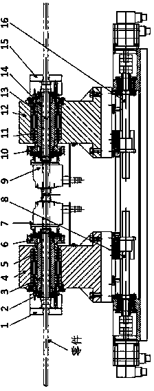
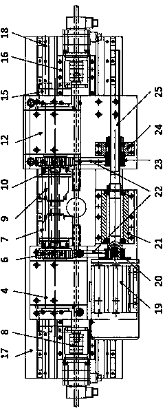
[0027] like figure 1 and 2 As shown, the clamping drive device for double-head turning of a slender shaft includes a left clamping unit, a right clamping unit and a power drive unit;

[0028] The left clamping unit includes a left hydraulic power chuck 1, a left pull rod 2, a left main shaft 3, a left main shaft case 4, a left main shaft bearing group 5, a left large synchronous pulley 6, and a left rotary oil cylinder 7; it is installed at the front end of the left main shaft 3 There is a left hydraulic power chuck 1, and a left rotary oil cylinder 7 is installed at the rear end, which is supported on the left main shaft case 4 through the left main shaft bearing group 5; a left pull rod 2 mechanism is arranged in the center of the main shaft, and the front end of the left pull rod 2 is connected with the left hydraulic power Chuck 1, the rear end is connected with the left rotary oil cylinder 7, through the control of the oil circuit connected to the left rotary oil cylinde...


PUM


Abstract

The invention discloses a long shaft double-head turning and clamping drive device and method. The long shaft double-head turning and clamping drive device comprises a left clamping unit, a right clamping unit and a power drive unit. A left clamping drive unit and a right clamping drive unit are installed on sliding blocks of a guide rail of a rack through a left main shaft box and a right main shaft box. A left Z-axis drive unit is arranged under the left clamping drive unit, a right Z-axis drive unit is arranged under the right clamping drive unit, and the power drive unit is installed on the side face of the left main shaft box. The long shaft double-head turning and clamping drive device has the advantages that the traditional mode of two-time clamping and two-time machining is replaced, and the production efficiency and capacity are improved; the clamping point of a long shaft component is clamped commonly through a left hydraulic power chuck and a right hydraulic power chuck, and flexibility can be achieved conveniently according to machined components of different sizes; the same power drive unit is adopted in left clamping unit and the right clamping unit, the long shaft component is commonly clamped, the clamping rigidity of the long shaft component is improved, and synchronism is good.

Description

technical field [0001] The invention relates to a slender shaft double-head turning clamping drive device and a method thereof, which belong to the field of mechanical processing and manufacturing, automation, and numerical control combined machine tools. Background technique [0002] In the current domestic and foreign automobile industry, before the forming and processing of a certain part involving a large number of applications, the raw material is a typical ultra-slender part. This part has an insurmountable processing technology, low processing accuracy, and poor product processing consistency. Bottleneck of inefficient production. At present, in China, the processing of the above-mentioned parts is usually completed by the numerical control transformation of ordinary lathe equipment. The processing method is to turn one end of the part; disassemble the part, turn around and clamp again, and turn the other end. low efficiency. In foreign countries, special equipment ...

Claims


Application Information

Patent Timeline
Patent Type & Authority Applications(China)
IPC IPC(8): B23B31/30
CPCB23B31/30
Inventor 黄小东姜杰凤郑国明郑希明
Owner 上海奇灏特自动化工程有限公司
Why Eureka
Try Eureka