Method of producing clamping force for a vehicle produced by an automatic parking brake

A parking brake and clamping force technology, applied in the direction of brakes, brake types, and axial brakes, etc., can solve the problems of long tracking time of the controller and increased component load, and achieve small volume accommodation, reduced component load, and reduced component load. Effect of small residual braking torque

Active Publication Date: 2019-06-07
ROBERT BOSCH GMBH
View PDF1 Cites 0 Cited by
  • Summary
  • Abstract
  • Description
  • Claims
  • Application Information

AI Technical Summary

Problems solved by technology

It may even be retensioned several times, which may lead to very long follow-up times of the control unit and thus to a higher load on the components, since the electric brake motor together with the transmission must be driven several times towards the pretensioned system startup

Method used


Image

  • Method of producing clamping force for a vehicle produced by an automatic parking brake
  • Method of producing clamping force for a vehicle produced by an automatic parking brake
  • Method of producing clamping force for a vehicle produced by an automatic parking brake

Examples


Embodiment Construction

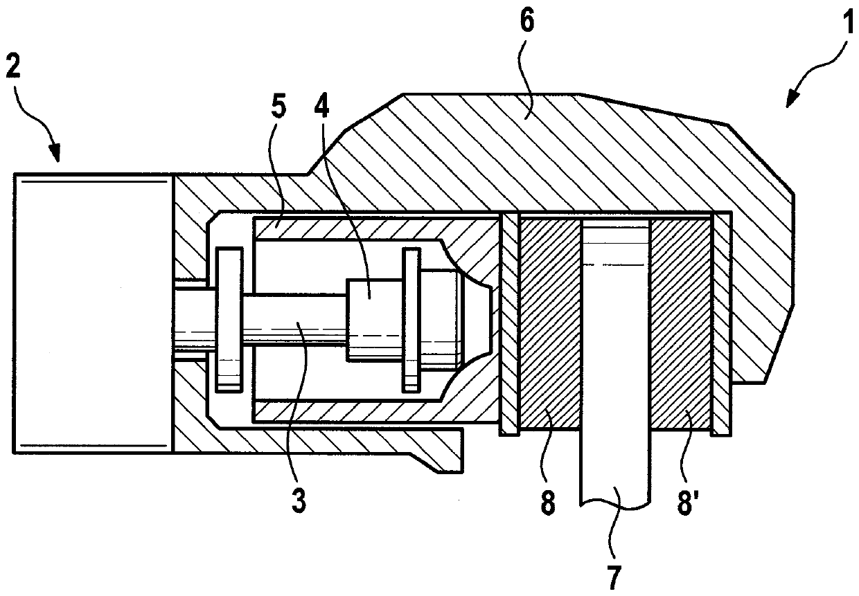
[0018] figure 1 A section is shown of a known automatic (automated) parking brake (parking brake) 1 for vehicles, which can exert a clamping force for immobilizing the vehicle by means of a brake motor 2 . The brake motor 2 is presently designed as an electric motor, which drives an axially mounted spindle 3 , in particular a spindle. On its end facing away from the brake motor 2 , the spindle 3 is equipped with a spindle nut 4 , which bears against the inner front or rear of the brake piston 5 . Spindle 3 , spindle nut 4 and brake piston 5 are mounted in a brake caliper 6 , which engages brake pads 7 in a caliper-like manner above. A brake friction layer 8 , 8′ is arranged on both sides of the brake pad 7 .

[0019] During the application process of the parking brake 1 , the spindle nut 4 is moved axially towards the brake piston 5 and the brake lining 7 by the rotation of the spindle 3 until a predetermined target clamping force is reached. In addition to the electromecha...


PUM


Abstract

The invention relates to a method for producing the clamping force for a vehicle produced by an automatic parking brake. Among them, the clamping force is generated by the brake piston (5) and the brake motor (2) acting on the brake pad (7). The technical problem to be solved by the present invention is to provide a method which ensures reliable operation of an automatic parking brake even in the event of a loss of clamping force due to temperature changes of the brake pads, and the method In addition, the load on the components of the automatic parking brake is minimized. For this purpose, after the completed application process of the automatic parking brake (1), the hydraulic pressure is built up in the brake circuit of the vehicle and the pressure loss gradient (dp / dt) in the brake circuit of the vehicle is determined ), wherein an automatic reapplying of the parking brake ( 1 ) takes place or does not take place depending on the ascertained pressure loss gradient (dp / dt).

Description

technical field [0001] The invention relates to a method for generating the clamping force produced by an automatic parking brake, a control or regulator and an automatic parking brake for a vehicle. Background technique [0002] An automatic parking brake for use in vehicles is known from DE 10 2011 005 842 A1, which can exert a clamping force on the brake pads in order to immobilize a stationary vehicle. The clamping force is generated here by the spindle nut and the brake piston, which are moved by the brake motor and tension the brake lining between the two brake friction layers during the pressing process. The brake piston can additionally be acted upon by a hydraulic brake fluid, which is achieved by conventional vehicle brakes (operating brakes). Due to the braking process performed while driving, heating or heating of the brake pads may occur. When immobilizing a stationary vehicle by means of the parking brake, the problem thus arises that the coefficient of frict...

Claims


Application Information

Patent Timeline
Patent Type & Authority Patents(China)
IPC IPC(8): B60T13/74
CPCB60T8/172B60T8/245B60T8/885B60T2270/406B60T13/588B60T13/741F16D55/226F16D2121/24F16D2125/40
Inventor D.布拉泰特F.贝尔勒-米勒
Owner ROBERT BOSCH GMBH
Why Eureka
Try Eureka