
Transmission shaft installation structure and vehicle having transmission shaft installation structure

A technology of installation structure and transmission shaft, which is applied in the field of vehicles, can solve problems such as poor rigidity, achieve the effects of reducing vibration, reducing beating, and prolonging service life

Inactive Publication Date: 2015-08-12
BEIJING BORGWARD AUTOMOBILE CO LTD
View PDF9 Cites 7 Cited by
  • Summary
  • Abstract
  • Description
  • Claims
  • Application Information

AI Technical Summary

Problems solved by technology

[0003] In view of this, the present invention proposes a transmission shaft installation structure, aiming to solve the problem of poor rigidity of the installation position of the longitudinal beam of the middle channel at the installation position of the transmission shaft installation bracket

Method used


Image

  • Transmission shaft installation structure and vehicle having transmission shaft installation structure
  • Transmission shaft installation structure and vehicle having transmission shaft installation structure
  • Transmission shaft installation structure and vehicle having transmission shaft installation structure

Examples


Embodiment Construction

[0020] Exemplary embodiments of the present disclosure will be described in more detail below with reference to the accompanying drawings. Although exemplary embodiments of the present disclosure are shown in the drawings, it should be understood that the present disclosure may be embodied in various forms and should not be limited by the embodiments set forth herein. Rather, these embodiments are provided for more thorough understanding of the present disclosure and to fully convey the scope of the present disclosure to those skilled in the art.

[0021] Embodiment of drive shaft installation structure:

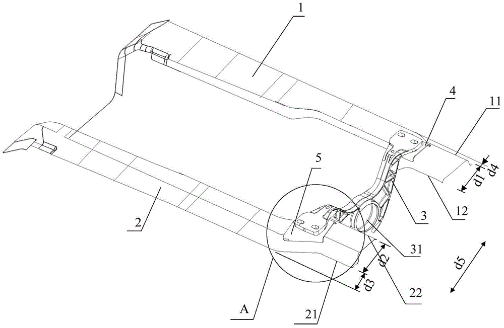
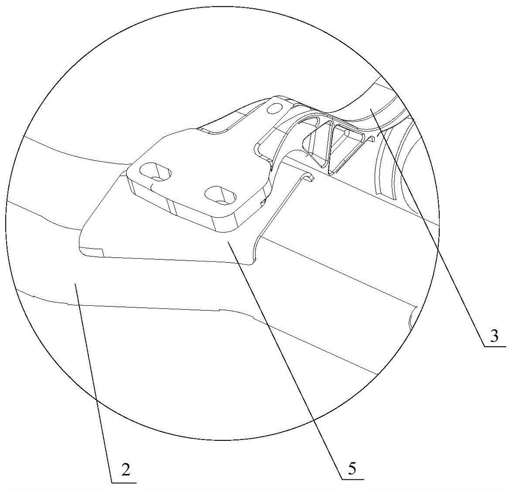
[0022] see figure 2 , which shows a schematic view of the drive shaft installation structure provided by the embodiment of the present invention. As shown in the figure, this embodiment includes a first longitudinal beam 1 , a second longitudinal beam 2 and a transmission shaft mounting bracket 3 whose two ends are respectively connected to the first longitudinal beam 1 a...


PUM


Abstract

The invention provides a transmission shaft installation structure and a vehicle having the transmission shaft installation structure. The transmission shaft installation structure comprises a first longitudinal beam, a second longitudinal beam and a transmission shaft installation bracket of which the two ends are connected to the first longitudinal beam and the second longitudinal beam, and a middle passage is arranged between the first longitudinal beam and the second longitudinal beam. The transmission shaft installation structure is characterized in that the outer wall of the position, connected with the transmission shaft installation bracket, of first longitudinal beam is bent towards the middle passage. As the outer wall, positioned on the right of the transmission shaft installation bracket, of first longitudinal beam is sunken towards the middle passage, compared with the prior art, the width of the first longitudinal beam which is positioned on the right of the transmission shaft installation bracket is decreased, thus the stiffness of the installation position, on the first longitudinal beam, of the transmission shaft installation bracket is greatly improved, the vibration frequency and stiffness of the transmission shaft installation bracket are further improved, the vibration, transmitted to a vehicle body, of a transmission shaft is reduced, the vibration of the vehicle body directly transmitted to passengers through seats, a steering wheel and a floor board is reduced, and therefore the riding comfort is improved.

Description

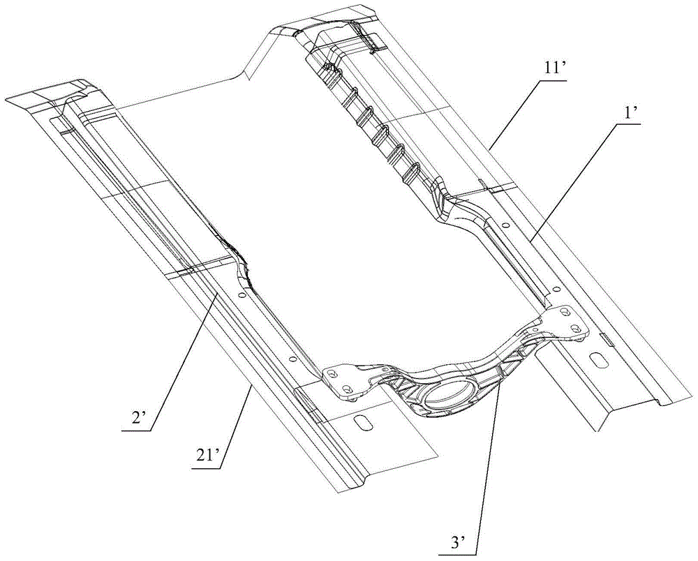
technical field [0001] The invention relates to the technical field of vehicles, in particular, to a transmission shaft installation structure and a vehicle with the transmission shaft installation structure. Background technique [0002] The transmission shaft is an important part of power transmission in the car transmission system. Its function is to transmit the power of the engine to the wheels together with the gearbox and drive axle, so that the car can generate driving force. see figure 1 , the transmission shaft is generally connected to the middle channel longitudinal beam of the vehicle body through the transmission shaft mounting bracket 3', specifically, the middle channel longitudinal beam includes the first longitudinal beam 1' and the second longitudinal beam 2', the first longitudinal beam 1 and the second longitudinal beam There is a middle channel between the two longitudinal beams 2', the two ends of the transmission shaft installation bracket 3' are res...

Claims


Application Information

Patent Timeline
Patent Type & Authority Applications(China)
IPC IPC(8): B62D21/09B60K17/24
Inventor 张媛
Owner BEIJING BORGWARD AUTOMOBILE CO LTD
Learn More