Machine for pouring fruits and vegetables out of boxes
A fruit and vegetable container dumping machine, fruit and vegetable technology, applied in the direction of emptying containers, loading/unloading, bottle filling, etc., can solve the problems of increasing the rate of secondary fruit, fast tipping speed, and affecting the efficiency of container dumping, so as to improve efficiency and guarantee tight fit effect
- Summary
- Abstract
- Description
- Claims
- Application Information
AI Technical Summary
Problems solved by technology
Method used
Image

Examples
Embodiment 1
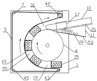
[0029] Such as figure 1As shown, embodiment 1 fruit and vegetable dumping machine, comprises frame 1, is provided with drum wheel 4, the 2nd driving roller 42, driven roller 43, the 3rd guide roller 7, the 4th guide roller 45 on the frame 1, the 4th guide roller 45, 2 The driving roller 42 is located above the drum 4, the driven roller 43 is located below the drum 4, the third guide roller 7 is located at the upper left of the drum 4, the fourth guide roller 45 is located at the lower left of the drum 4, the second Driving roller 42, driven roller 43, the 3rd guide roller 7, the 4th guide roller 45 are surrounded with pressing external belt 5, and drum 4 and the 2nd driving roller 42 all have power input, and drum 4 rotates clockwise, the 4th 2. The driving roller 42 rotates counterclockwise, and the pressing outer belt 5 is located on the left side of the drum 4. The outer circumferential surface of the drum 4 and the pressing outer belt 5 keep running synchronously, forming ...
Embodiment 2
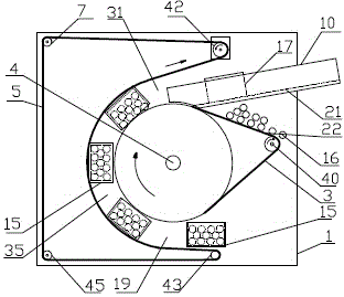
[0031] Such as figure 2 As shown, embodiment 2 fruit and vegetable box-turning machine comprises frame 1, is provided with drum wheel 4, the 2nd driving roller 42, driven roller 43, the 3rd guide roller 7, the 4th guide roller 45 and The first driving roller 40, the second driving roller 42 are located above the drum 4, the driven roller 43 is located below the drum 4, the third guide roller 7 is located on the upper left of the drum 4, and the fourth guide roller 45 is located on the drum 4, the 2nd driving roller 42, the driven roller 43, the 3rd guide roller 7, the 4th guide roller 45 are surrounded by the compression outer belt 5, the 1st driving roller 40 is positioned at the right side of the drum 4, the 1st driving roller 40 is positioned at the right side of the drum 4 The driving roller 40 and the drum 4 are surrounded by an inner belt 3, the first driving roller 40 and the second driving roller 42 have power input, the first driving roller 40 rotates clockwise, the ...
Embodiment 3
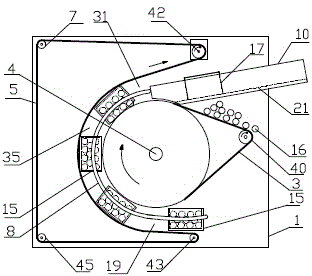
[0033] Such as image 3 As shown, on the basis of Embodiment 2, the conveying channel 35 is provided with a conveying guiding device. sides. Embodiment Other structure is the same as embodiment 2.
[0034] Each arc rod 8 of embodiment 3 is provided with arc rod adjusting device, as Figure 6 and Figure 7 As shown, the arc rod adjustment device includes a first lead screw 34 and a second lead screw 30, the first lead screw 34 is located on one side of the drum 4 and is fixed on the frame 1, and the first lead screw 34 is covered with The sliding sleeve 36 is fixed with a shaft sleeve 32, the shaft sleeve 32 is perpendicular to the sliding sleeve 36, the shaft sleeve 32 is set on the second lead screw 30, and the two ends of the sliding sleeve 36 are respectively provided with the first adjusting nut 55 and The second adjustment nut 56, the first adjustment nut 55 and the second adjustment nut 56 are compatible with the first lead screw 34; the two ends of the shaft sleeve ...
PUM
 Abstract
Description
Claims
Application Information
 - R&D
- Intellectual Property
- Life Sciences
- Materials
- Tech Scout
- Unparalleled Data Quality
- Higher Quality Content
- 60% Fewer Hallucinations
Browse by: Latest US Patents, China's latest patents, Technical Efficacy Thesaurus, Application Domain, Technology Topic, Popular Technical Reports.
© 2025 PatSnap. All rights reserved.Legal|Privacy policy|Modern Slavery Act Transparency Statement|Sitemap|About US| Contact US: help@patsnap.com