Novel composite bearing for forklifts

A technology of composite bearings and forklifts, which is applied in the direction of bearings, shafts and bearings, bearings for rotational motion, etc., can solve the problems of many parts, low service life, inconvenient assembly and processing, etc., to reduce parts, ensure accuracy, The effect of convenient processing

Active Publication Date: 2015-08-12
江苏如非轴承科技有限公司
View PDF5 Cites 3 Cited by
  • Summary
  • Abstract
  • Description
  • Claims
  • Application Information

AI Technical Summary

Problems solved by technology

However, it still has certain disadvantages: because the side roller bracket is cylindrical in shape, when in use, the side roller is against the forklift mast, and the forklift mast vibrates to a certain extent during the movement, so that the side roller bracket is easy to be in the shaft head. A certain deflection occurs, which makes the side rollers unable to work normally, accelerates wear and lowers the service life
[0004] In the above structure, the side roller is installed on the shaft head through the side ro

Method used


Image

  • Novel composite bearing for forklifts
  • Novel composite bearing for forklifts
  • Novel composite bearing for forklifts

Examples


Embodiment 1

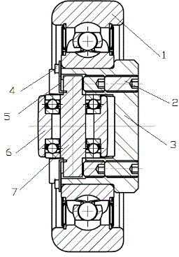
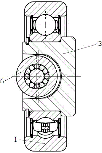
[0024] like figure 1 , figure 2 As can be seen from the schematic diagram shown, the first structure of the composite bearing for a forklift of the present invention includes a main roller 1 , a shaft head 3 and a side roller 6 .

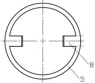
[0025] The main roller 1 is sleeved on the shaft head 3, and an annular limit groove is opened on one side of the top end surface of the shaft head 3, and an annular installation groove is opened at the corresponding position of the inner wall of the main roller 1. One side of the inner ring of the main roller 1 The position is limited by the stepped surface of the shaft head 3 itself, and the other end is limited by the retaining ring 4 embedded in the limit groove and the installation groove.

[0026] By directly installing the side roller 6 on the shaft head 3, this structure removes the side roller bracket, thereby reducing the components of the overall bearing, making the structure simple, and the corresponding assembly and processing are mor...

Embodiment 2

[0032] like Image 6 , Figure 7 As can be seen from the schematic diagram shown, the second structure of the composite bearing for a forklift of the present invention includes a main roller 11 , a shaft head 12 and a side roller 15 .

[0033] The main roller 11 is sleeved on the shaft head 12, one side of the inner ring of the main roller 11 is limited by the stepped surface of the shaft head 12 itself, and the other end of the main roller 11 is limited by the adjustment limit mechanism connected with the shaft head 2. .

[0034] By directly installing the side roller 11 on the shaft head 12, such a structure removes the side roller bracket, thereby reducing the components of the integral bearing, making the structure simple, and the corresponding assembly and processing are relatively convenient.

[0035] Depend on Figure 9 As can be seen from the schematic diagram shown, there is an inner cavity 19 with a cross-shaped cross section on the top surface of the shaft head 1...


PUM


Abstract

The invention relates to a novel composite bearing for forklifts, comprising a main roller, a spindle nose and a side roller. The main roller sleeves the spindle nose. The top end face of the spindle nose is provided with an inner cavity having a cross-shaped cross section, and the side roller is arranged in the inner cavity. The side roller rises above the top end face of the spindle nose. An adjusting and limiting mechanism for preventing the side roller from falling off is arranged at the top end face of the spindle nose. Threaded holes at the two sides of the bottom end face of the spindle nose are respectively connected with an adjusting bolt. The top ends of the two adjusting bolts respectively abut against the two ends of the side roller shaft of the side roller. The novel composite bearing for forklifts has the advantage that the number of components is reduced, the structure is simple and assembling and processing are convenient as a side roller bracket is removed and the side roller is directly mounted on the spindle nose.

Description

technical field [0001] The invention relates to a bearing, in particular to a novel composite bearing for forklift trucks. Background technique [0002] Bearings for forklift gantry need to realize rotational motion in two directions. Due to the limitation of space position, a compound roller structure with rotational motion in two directions is generally used, which has a built-in side roller bracket in a conventional bearing. Install side rollers on the roller bracket. For example, Patent Authorization Announcement No. CN 201250086Y discloses a forklift built-in side roller, which consists of a shaft head, a side roller bracket, a side roller, and a small shaft. The roller bracket mounts the side rollers through the small shaft. This structure has the advantages of compact structure and small volume, and is widely used in forklift mast bearings. However, it still has certain disadvantages: because the side roller bracket is cylindrical in shape, when in use, the sid...

Claims


Application Information

Patent Timeline
IPC IPC(8): B66F9/075F16C25/00
CPCB66F9/075F16C25/00
Inventor 闫生辉陈玉华沈贵生汪宝和冯爱军席玉珩
Owner 江苏如非轴承科技有限公司
Why Eureka
Try Eureka