Double-vibrator piezoelectric driving micro fan

A piezoelectric drive, micro fan technology, applied in the direction of generator/motor, piezoelectric effect/electrostrictive or magnetostrictive motor, machine/engine, etc., can solve the problem of weak output capacity of fan and limit the application of piezoelectric fan And other issues

Inactive Publication Date: 2015-08-12
长春隆美科技发展有限公司
View PDF0 Cites 14 Cited by
  • Summary
  • Abstract
  • Description
  • Claims
  • Application Information

AI Technical Summary

Problems solved by technology

In the past, the power source of the piezoelectric fan is generally a piece of piezoelectric vibrator. Due to the small deformation of the piezoelectric vibrator, the maximum displacement of the center is generally less than 20 microns, so the output capacity of the fan is weak, which limits the application of the piezoelectric fan in various fields. application

Method used


Image

  • Double-vibrator piezoelectric driving micro fan
  • Double-vibrator piezoelectric driving micro fan

Examples


Embodiment Construction

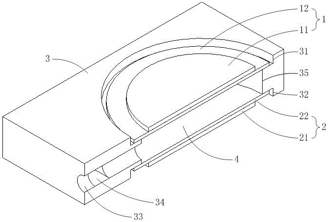
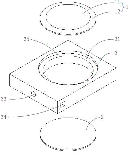
[0012] refer to figure 1 and figure 2 , the dual vibrator piezoelectric driven fan of the present invention is composed of a first piezoelectric vibrator 1, a second piezoelectric vibrator 2 and a base 3, wherein:

[0013] The first piezoelectric vibrator 1 is formed by bonding a piezoelectric material sheet 11 and an elastic substrate 12 , and the second piezoelectric vibrator 2 is formed by bonding a piezoelectric material sheet 11 and an elastic substrate 12 .

[0014] The base body 3 is a flat rectangular block. The first piezoelectric vibrator installation groove 31 is arranged on the top surface of the base body 3, and the second piezoelectric vibrator installation groove 32 is arranged on the bottom surface of the base body 3. The depth of the first piezoelectric vibrator installation groove 31 is greater than that of the first piezoelectric vibrator installation groove. The sum of the total thickness of the piezoelectric vibrator 1 and the peak value of the central d...


PUM


Abstract

The invention relates to a double-vibrator piezoelectric driving micro fan comprising two piezoelectric vibrators and a substrate. The substrate is a flat rectangular block, a pair of piezoelectric vibrator installation grooves is arranged symmetrically in the top and bottom surfaces of the substrate, and a run-through middle hole is arranged between the bottom surfaces of the two installation grooves. The two piezoelectric vibrators are respectively installed in the two piezoelectric vibrator installation grooves of the substrate, and the two piezoelectric vibrators and the middle hole of the substrate form a middle cavity. One side of the substrate is provided with an outlet hole which communicates the middle cavity with outside air. An inlet hole is arranged in the vertical direction of the outlet hole. During working, the two piezoelectric vibrators bend inward or outward and vibrate at the same time, the size of the middle cavity is reduced or increased, fluid flows into or out of the outlet hole, and gas flows into the inlet hole or flows out of the outlet hole, thus forming directional fluid drive capability output by gas from the outlet hole. The amount of volume change of the cavity in each cycle is significantly greater than that of a traditional single-vibrator piezoelectric fan. The output capability of the piezoelectric fan can be improved.

Description

technical field [0001] The invention belongs to the field of fluid transportation, and in particular relates to a piezoelectric-driven micro fan with double vibrators. Background technique [0002] Piezoelectric fan is a fluid drive device with piezoelectric vibrator as the power source. Its function is to provide a certain flow of gas at the outlet. It can be used for active cooling, gas transportation, pneumatic drive etc. It has the advantages of simple structure for mass production, small size for miniaturization, digital control and long life. In the past, the power source of the piezoelectric fan is generally a piece of piezoelectric vibrator. Due to the small deformation of the piezoelectric vibrator, the maximum displacement of the center is generally less than 20 microns, so the output capacity of the fan is weak, which limits the application of the piezoelectric fan in various fields. application. Contents of the invention [0003] In order to solve the probl...

Claims


Application Information

Patent Timeline
Patent Type & Authority Applications(China)
IPC IPC(8): F04B45/047H02N2/04
Inventor 吴越王志军李蒙蒙黄然涂前进岳子正
Owner 长春隆美科技发展有限公司
Why Eureka
Try Eureka