A Cooling Structure of Centrifugal Water Pump Shaft Seal

A technology of centrifugal water pump and cooling structure, which is applied to parts, pumps, and pump elements of pumping devices used for elastic fluids. It can solve the problems of turning back heat and cannot be cooled, and achieve the effect of avoiding shaft seal damage and prolonging the service cycle.

Active Publication Date: 2017-08-11
江苏汉盛海洋装备技术有限公司
View PDF4 Cites 0 Cited by
  • Summary
  • Abstract
  • Description
  • Claims
  • Application Information

AI Technical Summary

Problems solved by technology

[0004] The purpose of the present invention is to solve the problem that the shaft seal of the water pump in the prior art cannot be cooled when the water pump turns and heats up, and discloses a cooling structure for the shaft seal of the centrifugal water pump. A shaft seal cooling structure is added to the seal seat, which not only facilitates the discharge of all the gas in the shaft seal chamber when pre-filling the water pump, but also forms a shaft seal cooling circuit composed of water flow and the shaft seal chamber, and timely leads out the two contacting end surfaces of the shaft seal. frictional heat

Method used


Image

  • A Cooling Structure of Centrifugal Water Pump Shaft Seal
  • A Cooling Structure of Centrifugal Water Pump Shaft Seal
  • A Cooling Structure of Centrifugal Water Pump Shaft Seal

Examples


Embodiment Construction

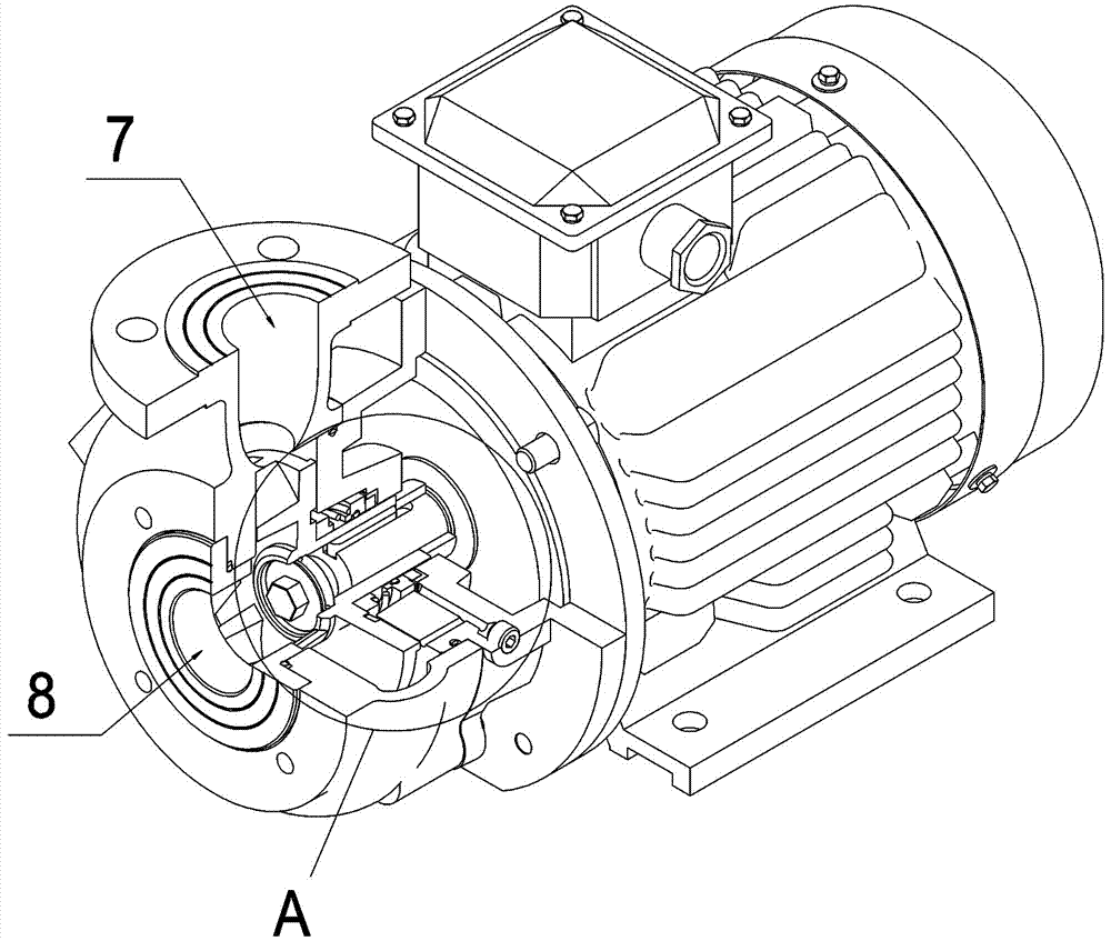
[0012] According to attached Figure 1~4 , the present invention is a cooling structure for a shaft seal of a centrifugal water pump. A flow channel 6 is arranged inside the shaft seal seat 4 of the centrifugal water pump. The flow channel 6 is composed of two mutually perpendicular and intersecting through holes, one of which is connected with The axis of the shaft seal seat 4 is parallel to the through hole on the outside of the shaft seal seat, and the other through hole is a radially arranged through hole perpendicular to the axis of the shaft seal seat 4. A sealing plug is set at the orifice, and the sealing plug is a spiral plug 5. The hole diameter of the flow channel 6 is 3 mm to 10 mm, and the inner wall of the orifice is provided with an internal thread matched with the thread of the helical plug 5 .

[0013] When the water pump is prefilled with water, the screw plug 5 is unscrewed earlier, and then the screw plug 5 is tightened again when a stream of water flows o...


PUM


Abstract

The invention discloses a cooling structure of a centrifugal pump shaft seal. The cooling structure is characterized in that a flow channel is arranged in a centrifugal pump shaft seal base, the flow channel is composed of two through holes which are perpendicular to each other and intersect, one through hole is parallel to the axis of the shaft seal base and is close to the outer side of the shaft seal base, the other through hole is perpendicular to the axis of the shaft seal base and is arranged in the radial direction, and a blocking stopper is arranged at the hole opening, leading to the exterior of the shaft seal base, of the through hole which is arranged in the radial direction; when a centrifugal pump works, water pressure around an impeller and water pressure in the flow channel are larger than water pressure in a shaft seal cavity of the shaft seal base, water flows into the shaft seal cavity through the flow channel, the water in the shaft seal cavity is thrown out along with back blades of the impeller, a loop is formed, and friction heat of contact end faces of a static shaft seal ring and a movable shaft seal is guided out in time. By means of the flow channel structure, air in the cavity can be exhausted conveniently when a pump conducts water pre-filling, the friction heat of the contact end faces of the static shaft seal ring and the movable shaft seal ring can be guided out in time, and the service period of the pump is greatly prolonged.

Description

technical field [0001] The invention relates to a cooling structure for a shaft seal of a water pump, and in particular discloses a cooling structure for a shaft seal of a centrifugal water pump. By adding a structure to the shaft seal seat of the water pump, a cooling water circuit is formed with the shaft seal chamber to solve the problem of the shaft seal of the water pump. The problem that the heat cannot be cooled when the water pump turns back and forth is solved. Background technique [0002] Water pumps are widely used in the crushing and transportation of sewage, dirty oil, etc. Due to equipment installation and operating conditions, vertical installation is often used. Before the water pump runs, the water pump needs to be pre-filled with water. At this time, the shaft seal chamber is at the highest point in the pump body, and it is difficult to completely discharge the internal gas. When the water pump starts to run normally, the contact surface of the shaft seal...

Claims


Application Information

Patent Timeline
Patent Type & Authority Patents(China)
IPC IPC(8): F04D29/10F04D29/58
CPCF04D29/106F04D29/58
Inventor 顾耀民陈亚军邱伯龙
Owner 江苏汉盛海洋装备技术有限公司
Why Eureka
Try Eureka