cable tie

A cable and master tape technology, applied in the direction of pipe supports, mechanical equipment, pipes/pipe joints/pipe fittings, etc., can solve the problem of spending more manpower, and achieve the effect of simple structure, beautiful engineering, and reduced labor intensity.

Inactive Publication Date: 2018-11-06
STATE GRID SHANDONG ELECTRIC POWER +1
View PDF6 Cites 0 Cited by
  • Summary
  • Abstract
  • Description
  • Claims
  • Application Information

AI Technical Summary

Problems solved by technology

The workflow of cable binding in the traditional method is that after the construction personnel lay the cables connected to the equipment in layers according to the construction drawings, they lay the cables in order from the inside to the outside, and then tie the cables one by one at the cable bracket. Bundle the cables next to each other. When there are many cables to be laid and the single cable is long, it will take more manpower to bundle the cables, and the time required is about 1 / 10 of the entire construction period.

Method used


Image

  • cable tie
  • cable tie
  • cable tie

Examples


Embodiment 1

[0024] A cable tie includes a cable tie mother belt and several cable tie sub-bands. Both the cable tie master strap and the cable tie sub-tie are cable ties made of nylon material.

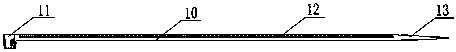
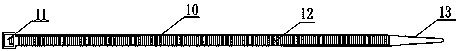
[0025] Such as figure 1 , figure 2 As shown, the cable tie master includes a master body 10, the first end of the master body 10 is fixedly provided with a master lock 11, and the master body 10 is provided with a master stop mechanism 12; the master body 10 The second end of the master tape is provided with a flat tip 13 .

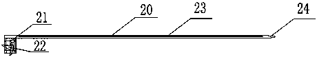
[0026] Such as image 3 , Figure 4 As shown, the cable tie sub-strap includes a sub-strap body 20, the first end of the sub-strap body 20 is provided with a sub-strap main lock 21, and the side of the sub-strap main lock 21 is fixedly provided with a sub-strap side lock 22. The main body 20 is provided with a sub-belt stop mechanism 23 , and the second end of the sub-belt body 20 is provided with a sub-belt flat tip 24 .

[0027] The sub-tape main locking opening 21 ...

Embodiment 2

[0032] A cable tie includes a cable tie mother belt and several cable tie sub-bands. Both the cable tie master strap and the cable tie sub-tie are cable ties made of nylon material.

[0033] Such as figure 1 , figure 2 As shown, the cable tie master includes a master body 10, the first end of the master body 10 is fixedly provided with a master lock 11, and the master body 10 is provided with a master stop mechanism 12; the master body 10 The second end of the master tape is provided with a flat tip 13 .

[0034] Such as image 3 , Figure 4 As shown, the cable tie sub-strap includes a sub-strap body 20, the first end of the sub-strap body 20 is provided with a sub-strap main lock 21, and the side of the sub-strap main lock 21 is fixedly provided with a sub-strap side lock 22. The main body 20 is provided with a sub-belt stop mechanism 23 , and the second end of the sub-belt body 20 is provided with a sub-belt flat tip 24 .

[0035] The side locking opening 22 of the su...


PUM


Abstract

The invention, which belongs to the attachment tools for power work, discloses a cable band comprising a master cable band and a plurality of sub cable bands. The master cable band includes a master band body; a master band locking port is fixedly arranged at a first end portion of the master band body; and a master band retaining mechanism is arranged at the master band body. The sub cable bands contain sub band bodies; sub band main locking ports are arranged at first end portions of the sub band bodies and sub band side locking ports are fixedly arranged at the sides of the sub band main locking ports; and sub band retaining mechanisms are arranged at the sub band bodies. The sub band main locking ports or sub band side locking ports pass through the master band body and are in a clamping fit relation with the master band retaining mechanism. According to the invention, the cable band includes the master cable band and the multiple sub cable bands, and the sub band side locking ports are arranged at the sub cable bands. When each two cables are laid, the sub cable bands can penetrate the sub band side locking ports at the last stage, so that the stage-to-stage connection is realized and the binding is firm and an aesthetic effect is realized. With the cable band, the cable binding efficiency during construction of a newly-built transformer substation or modification of an old transformer substation can be improved by 220%.

Description

technical field [0001] The invention relates to the field of electric power operation accessories, in particular to a cable tie. Background technique [0002] In the construction of new substations and renovation projects, there are many problems when the control cables connected to the equipment need to be tied flatly on the cable support layer in the order from the inside to the outside. The workflow of cable binding in the traditional method is that after the construction personnel lay the cables connected to the equipment in layers according to the construction drawings, they lay the cables in order from the inside to the outside, and then tie the cables one by one at the cable bracket. When there are many cables to be laid and the single cable is long, it will take more manpower to bundle the cables, and the time required accounts for about 1 / 10 of the entire construction period. Therefore, how to improve efficiency and reduce labor intensity on the basis of ensuring c...

Claims


Application Information

Patent Timeline
Patent Type & Authority Patents(China)
IPC IPC(8): F16L3/137
CPCF16L3/137
Inventor 张峰杨军马波樊稳稳宋亚波何良吴婷张颖刘亚丽
Owner STATE GRID SHANDONG ELECTRIC POWER
Why Eureka
Try Eureka