Supercharge Your Innovation With Domain-Expert AI Agents!

Hot stamping machine

A technology of hot embossing equipment and embossing equipment, which is applied in the direction of metal processing equipment, printing, printing machines, etc., which can solve the problems of enlarging, manual cleaning and stripping edges of hot embossing equipment, and achieve the effect of avoiding overheating

Active Publication Date: 2015-08-12
LEONHARD KURZ STIFTUNG & CO KG
View PDF4 Cites 4 Cited by
  • Summary
  • Abstract
  • Description
  • Claims
  • Application Information

AI Technical Summary

Problems solved by technology

Due to the contamination of the peeling edge, the friction at the peeling edge increases so strongly over time that the operation of the hot embossing system has to be interrupted and the peeling edge has to be cleaned manually

Method used


Image

  • Hot stamping machine
  • Hot stamping machine
  • Hot stamping machine

Examples


Embodiment Construction

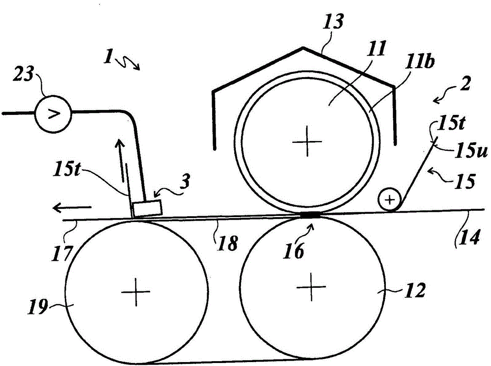
[0033] figure 1 A thermal embossing device 1 is shown, which has an embossing device 2 and a stripping device 3 . The embossing apparatus 2 includes an embossing roller 11 , a counter-pressing roller 12 and a heating device 13 .

[0034] The embossing roller 11 has a coating 11b made of an elastomer on its outer circumference. The elastomer is preferably silicone rubber. The counter pressure roller 12 is made of steel.

[0035] The heating device 13 is arranged above the embossing roller 11 and figure 1 In the exemplary embodiment shown, it is designed as an infrared radiation heating device controlled by means of a temperature controller.

[0036] Upstream of the embossing device 2 , the substrate 14 to be embossed and the hot embossed film 15 are fed, said substrate and said hot embossed film being formed in the embossing nip formed between the embossing roller 11 and the counter-embossing roller 12 16 are connected to each other under the condition of forming embossing...


PUM

PropertyMeasurementUnit
thicknessaaaaaaaaaa
thicknessaaaaaaaaaa
thicknessaaaaaaaaaa

Abstract

The invention relates to a hot stamping machine (1), comprising a stamping device (2) for transferring a transfer layer (15u) arranged on a carrier layer (15t) of a hot stamping foil (15) onto a substrate (14). The hot stamping machine comprises a heatable stamping roller (11) and a counter-pressure roller (12) between which a stamping gap (16) is defined and in which gap a stamped substrate (17) is produced, and a downstream releasing device (3) for releasing the carrier layer (15t) from the stamped substrate (17). The releasing device (3) comprises a releasing element (20) which is designed as a bar-shaped hollow body on which a supply line for a pressurized gas (21) is arranged. At least one longitudinal edge of the releasing element (20) is designed as a perforated releasing edge (20k) having outlet openings (20a) for the pressurized gas (22) to produce a gas cushion between the carrier layer (15t) and the releasing element (20). The releasing edge (20k) is arranged transversely to the machine direction and in parallel to the upper face of the coated substrate (17).

Description

technical field [0001] The invention relates to a thermal embossing device according to the preamble of the subject-matter of claim 1 . Background technique [0002] Thermal embossing equipment is used to transfer the transfer layer provided on the carrier layer of the thermal embossing film to the substrate under the action of temperature and pressure. For this purpose, a heated embossing roller is provided, which interacts with a counter-pressure roller. Downstream of the embossing nip formed between embossing roller and counter roller, the carrier layer is detached from the transfer layer which has been transferred to the substrate by means of a stripping device. When using embossing rollers with a concave-convex profile and / or when using an adhesive layer which is applied to the substrate only in defined surface areas (the transfer layer adheres to the adhesive layer according to the design of the adhesive layer) , only part of the transfer layer is transferred to the ...

Claims


Application Information

Patent Timeline
Patent Type & Authority Applications(China)
IPC IPC(8): B41F16/00B44B5/00B44B5/02B41F19/06B44C1/17
CPCB41F16/0026B41P2219/22B41F19/062B29C65/78B29C65/80B65H41/00B41F16/006B21D37/16B41F16/002
Inventor R·比贝尔
Owner LEONHARD KURZ STIFTUNG & CO KG
Features
  • R&D
  • Intellectual Property
  • Life Sciences
  • Materials
  • Tech Scout
  • Unparalleled Data Quality
  • Higher Quality Content
  • 60% Fewer Hallucinations
Learn More