Reactant flow channels for electrolyzer applications

A technology of electrolyzer and channel, applied in the field of electrolyzer, can solve the problem of limiting the rate of electrochemical oxidation

Active Publication Date: 2015-08-12
LOOP ENERGY INC
View PDF7 Cites 2 Cited by
  • Summary
  • Abstract
  • Description
  • Claims
  • Application Information

AI Technical Summary

Problems solved by technology

In contrast, in electrolysis mode, longer serpentine flow field channels are unfavorable due to the generated regions of gas (hydrogen and oxygen) accumulating in the channel, preventing the supply of water to the electrodes, and limiting the reaction The rate of electrochemical oxidation of water

Method used


Image

  • Reactant flow channels for electrolyzer applications
  • Reactant flow channels for electrolyzer applications
  • Reactant flow channels for electrolyzer applications

Examples


Embodiment Construction

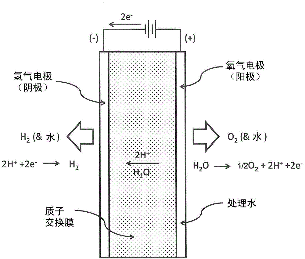
[0055] The electrolyzer assembly includes a flow field plate including at least one channel, wherein the cross-sectional area of ​​the channel varies along at least a portion of the length of the channel. In a preferred embodiment, the channel width decreases according to a natural exponential function in the direction of reactant flow along at least a portion of the channel length. The use of this type of improved flow field channel, in particular at the oxygen electrode (electrolyzer anode) can improve the performance and / or efficiency of the operation of the electrolyzer assembly.

[0056] Without being bound by theory, the following discussion, equations, and mathematical models may help explain at least some of the basis for the various advantages that may be realized using the embodiments of the invention described herein.

[0057] One approach is to design the electrolyzer anode flow channel for a substantially constant water velocity such that the electrolyzer anode fl...


PUM


Abstract

An electrolyzer or unitized regenerative fuel cell has a flow field comprising at least one channel, wherein the cross-sectional area of the channel varies along at least a portion of the channel length. In some embodiments the channel width decreases along at least a portion of the length of the channel according to a natural exponential function. The use of this type of improved flow field channel can improve performance and efficiency of operation of the electrolyzer device.

Description

[0001] Cross References to Related Applications [0002] This application is related to and claims U.S. Provisional Patent Application No. 61 / 712,010, filed October 10, 2012, U.S. Provisional Patent Application No. 61 / 712,236, also filed October 10, 2012, and March 15, 2013 Priority benefit of U.S. Provisional Patent Application No. 61 / 801,532, the disclosures of which are hereby incorporated by reference in their entirety. This application also relates to and claims the benefit of priority to International Application No. PCT / CA2013 / 050626, filed August 14, 2013, and International Application No. PCT / CA2013 / 050627, also filed August 14, 2013, of which The disclosure of is hereby incorporated by reference in its entirety. technical field [0003] The present invention relates generally to electrolyzers and, in particular, to fluid flow channels and flow fields for electrolyzers, and electrolyzers and electrolyzer stacks incorporating such fluid flow channels and flow fields. ...

Claims


Application Information

Patent Timeline
Patent Type & Authority Applications(China)
IPC IPC(8): C25B1/10C25B11/02H01M8/18C25B9/23
CPCH01M8/186C25B11/02H01M8/04768C25B1/10H01M8/04955H01M8/026Y02E60/528H01M16/006H01M8/0247H01M8/04753C25B15/08C25B1/04C25B9/73C25B9/23Y02E60/36Y02E60/50Y02E60/10C25B1/02H01M8/18
Inventor 肖恩·迈克尔·麦金农马太·保罗·保内拉乌尔·雅各布·金马格雷格·约翰·蒙铁
Owner LOOP ENERGY INC
Why Eureka
Try Eureka