
High temperature-type unitized regenerative fuel cell using water vapor and method of operating the same

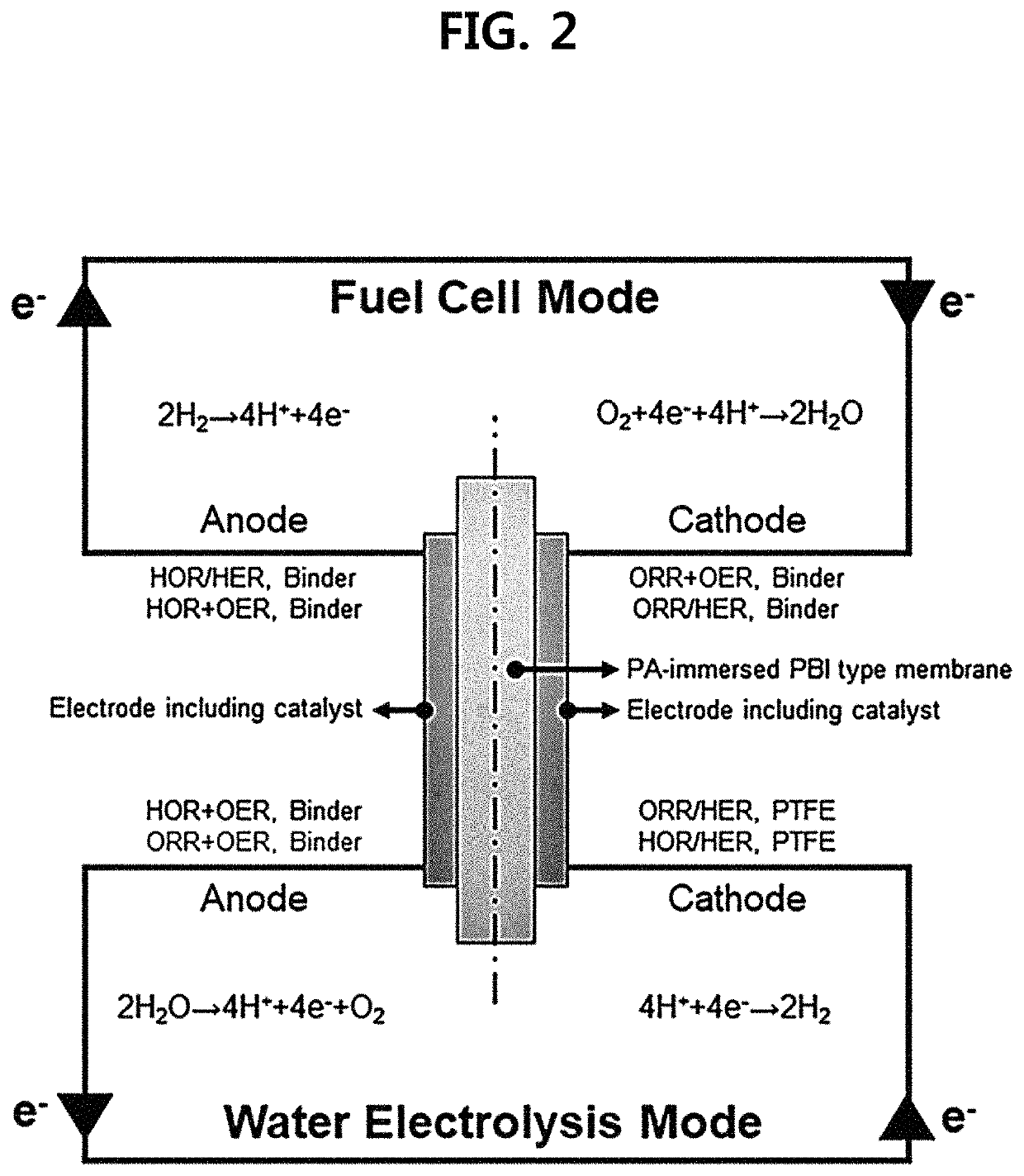
a regenerative fuel cell, high temperature technology, applied in the direction of cell components, electrochemical generators, electrolysis components, etc., can solve the problems of low humidity environment, reduced ion conductivity of polymer electrolyte membranes, and disadvantages of r-pemfc systems in space and cost, and achieve low threshold voltage, high heat recovery rate, and easy miniaturization

Active Publication Date: 2021-09-21
KOREA INST OF SCI & TECH
View PDF15 Cites 0 Cited by
  • Summary
  • Abstract
  • Description
  • Claims
  • Application Information

AI Technical Summary

Benefits of technology

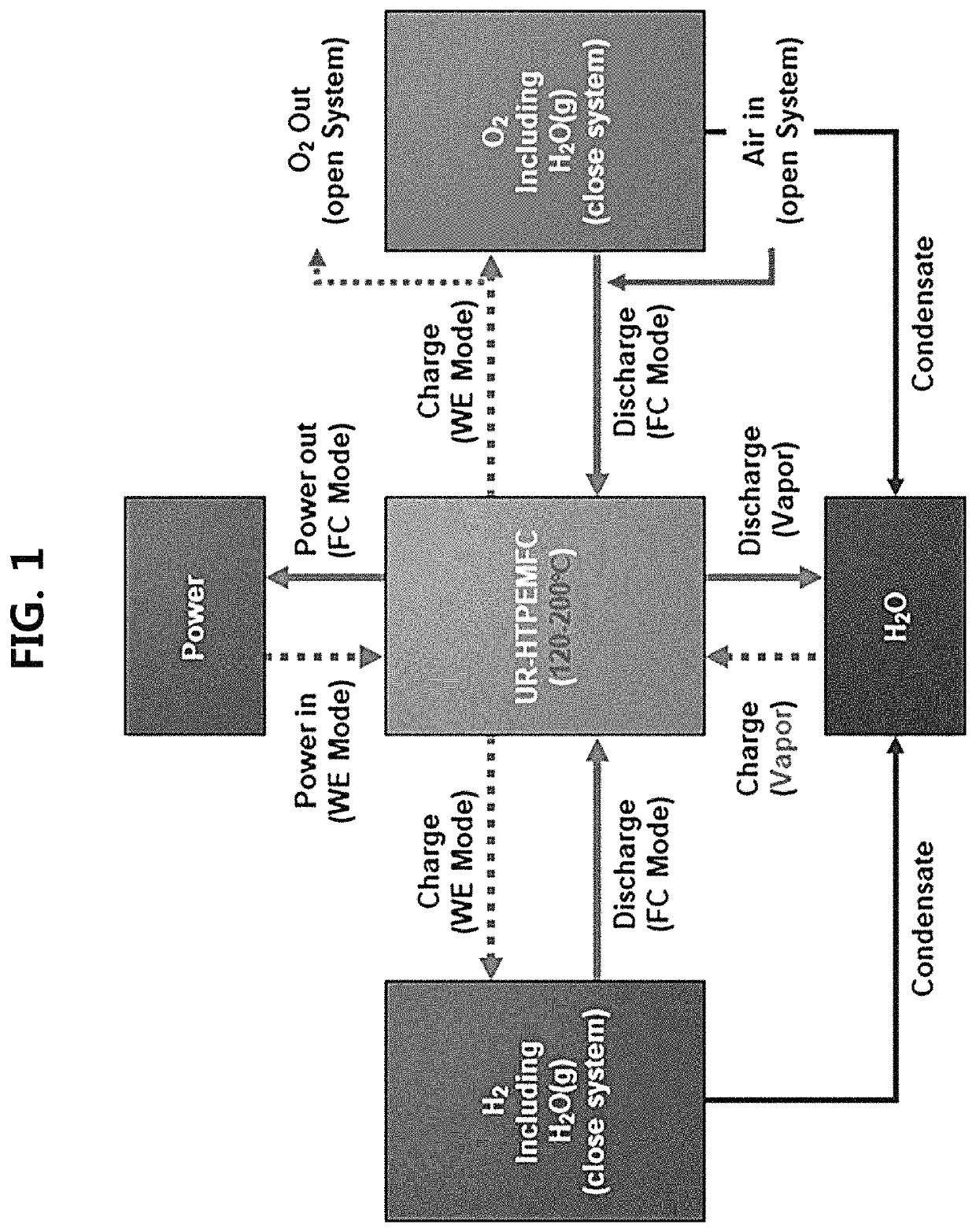
[0015]The unitized regenerative fuel cell according to exemplary embodiments of the present disclosure exhibits relatively higher heat recovery rate as compared to the existing UR-PEMFC due to high operating temperature (120-200° C.). In addition, it has low threshold voltage and can be operated in a fuel cell (FC) mode even with low-purity hydrogen. Furthermore, the system can be miniaturized easily because a humidifier is unnecessary. In addition, the problem due to the loss and leakage of phosphoric acid is decreased since the system is a closed system wherein water and gas are circulated in the fuel cell (FC) mode and the water electrolysis (WE) mode. In addition, the unitized regenerative high temperature-type polymer electrolyte membrane fuel cell (UR-HTPEMFC) is expected to be a very suitable energy storage and power generation system in the next-generation smart grid power generation system due to the energy storage through use of surplus power by the URFC.

Problems solved by technology

However, the R-PEMFC system is disadvantageous in terms of space and cost since the fuel cell and the water electrolysis unit are not unitized.
However, since the PEM used in the UR-PEMFC is mostly based on Nafion, there are limitations in that the ion conductivity of the polymer electrolyte membrane is decreased under low-humidity environments and the operating temperature should be maintained low in order to avoid the melting of the polymer membrane at high temperatures (non-patent document 3: Sadhasivam, T., et al.
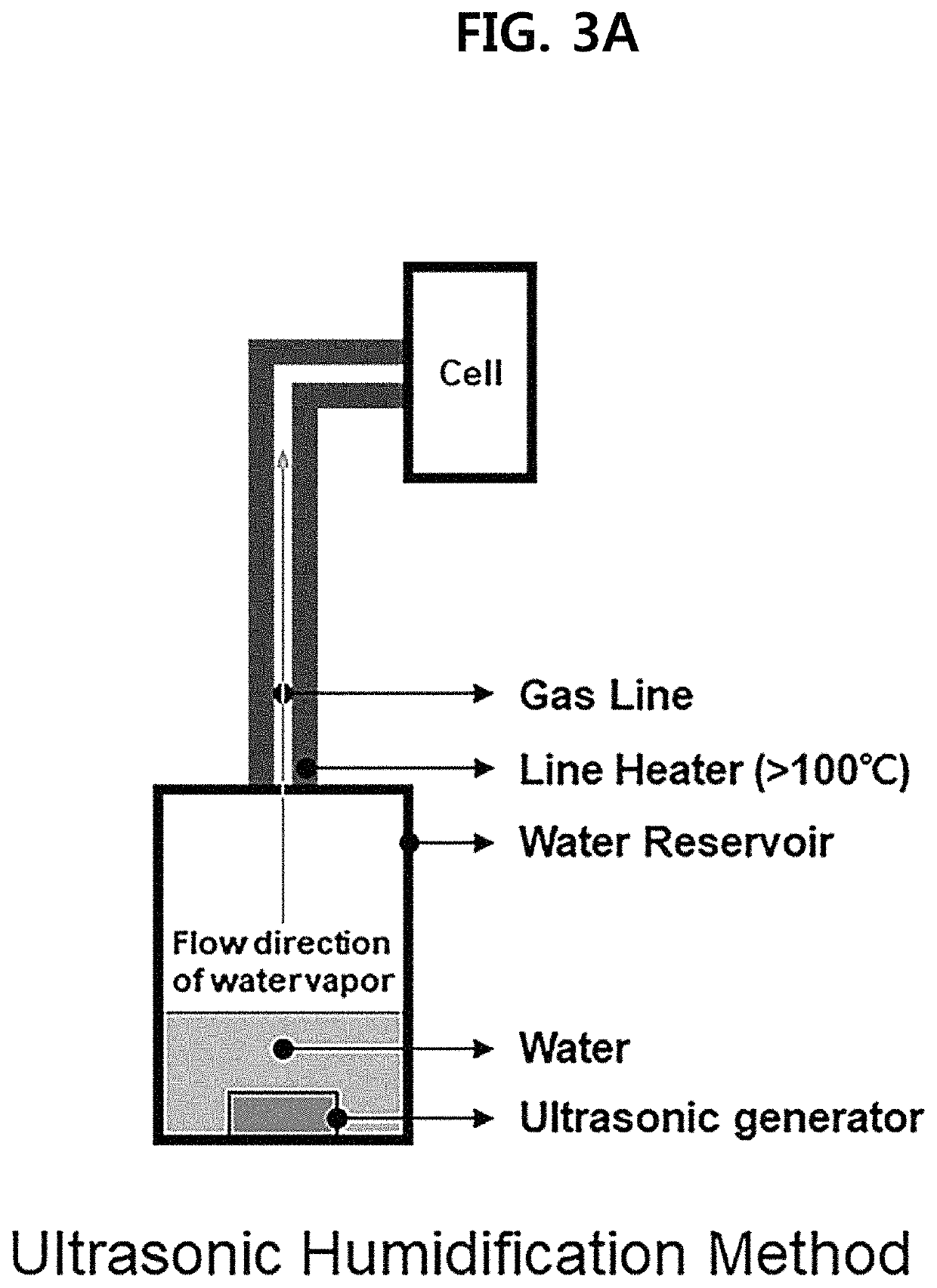
Furthermore, the system can be miniaturized easily because a humidifier is unnecessary.
In addition, the problem due to the loss and leakage of phosphoric acid is decreased since the system is a closed system wherein water and gas are circulated in the fuel cell (FC) mode and the water electrolysis (WE) mode.

Method used


Image

  • High temperature-type unitized regenerative fuel cell using water vapor and method of operating the same
  • High temperature-type unitized regenerative fuel cell using water vapor and method of operating the same
  • High temperature-type unitized regenerative fuel cell using water vapor and method of operating the same

Examples


examples

[0063

example

[0064][Example] Preparation of First Electrode

[0065]A first electrode including: a titanium substrate; an iridium oxide (IrO2) layer formed on the substrate through electroplating; and a platinum (Pt / C) layer formed on the iridium oxide (IrO2) layer through spraying was prepared.

[0066]Specifically, iridium chloride hydrate (IrCl4—H2O), oxalic acid ((COOH)2.2H2O), hydrogen peroxide (35% H2O2) and anhydrous potassium carbonate were added to deionized (DI) water and subjected to magnetic stirring for 3 days.

[0067]Iridium oxide plating was performed on a titanium substrate at 0.7 V (vs. SCE) for 10 minutes using the prepared solution. After adding polytetrafluoroethylene (PTFE, 25%), deionized water and isopropyl alcohol to 46.2% Pt / C, a catalyst slurry was prepared through ultrasonic dispersion.

[0068]Then, Pt / C was coated on the prepared electrode so that an amount of the platinum (Pt) catalyst was 0.2 mg / cm2.

[0069]The prepared electrode was used as an oxidation electrode (anode) in bo...


PUM

PropertyMeasurementUnit
operating temperatureaaaaaaaaaa
temperaturesaaaaaaaaaa
boiling pointaaaaaaaaaa

Abstract

Disclosed is a high temperature-type unitized regenerative fuel cell using water vapor, which exhibits high hydrogen (H2) production efficiency and superior power generation ability.

Description

CROSS-REFERENCE TO RELATED APPLICATION[0001]This application claims the priority of Korean Patent Application No. 10-2019-0109001, filed on Sep. 3, 2019, and all the benefits accruing therefrom under 35 U.S.C. § 119, the contents of which in their entirety are herein incorporated by reference.BACKGROUND1. Field[0002]The present disclosure relates to a high temperature-type unitized regenerative fuel cell (URFC) using water vapor and a method of operating the same. More specifically, the URFC of the present disclosure can be operated at high temperatures of 120° C. or above while minimizing the flow rate of water in liquid form by supplying water vapor to a first electrode including an OER (oxygen evolution reaction) catalyst during water electrolysis operation and has high water electrolysis efficiency and thermal efficiency due to low threshold voltage of hydrogen production by water electrolysis.[0003][Description of Government-Supported Research and Development][0004]This researc...

Claims


Application Information

Patent Timeline
Patent Type & Authority Patents(United States)
IPC IPC(8): H01M8/18H01M8/1004H01M8/1231H01M4/92H01M4/86H01M4/90H01M8/1018
CPCH01M8/186H01M4/8657H01M4/9025H01M4/92H01M8/1004H01M8/1231H01M2008/1095H01M2300/0068C25B13/08C25B1/042C25B9/23C25B11/032C25B11/052C25B11/063C25B11/081C25B11/089H01M4/8615H01M4/9016H01M4/9041H01M4/921H01M4/923H01M8/0232H01M8/0234H01M8/04089H01M8/103H01M8/1048Y02E60/36Y02E60/50
Inventor PARK, HYUN SEOLIM, AHYOUNLEE, JU SUNGPARK, HEE-YOUNGLEE, SO YOUNGKIM, JIN YOUNGYOO, SUNG JONGHENKENSMEIER, DIRKJANG, JONG HYUNKIM, HYOUNG-JUHN
Owner KOREA INST OF SCI & TECH
Learn More