Catalytic combustion bed core structure with heater

A catalytic combustion bed and heater technology, applied in the direction of combustion using catalytic materials, incinerators, combustion methods, etc., can solve the problem of reducing the combustion efficiency of industrial volatile organic pollutants, the uneven temperature of the furnace core structure, and the impact of catalytic combustion purification rate and other issues, to achieve the effect of uniform reflow, fast heating speed and high temperature

Inactive Publication Date: 2015-09-02
赛智环保科技(天津)有限公司
View PDF6 Cites 0 Cited by
  • Summary
  • Abstract
  • Description
  • Claims
  • Application Information

AI Technical Summary

Problems solved by technology

[0002] The core structure of the existing catalytic combustion bed is usually made of heat-resistant steel plates or industrial kiln masonry materials, which mainly deal with industrial volatile organic pollutants that are most harmful to people's health in PM2.5. In the core structure, the air inlet and outlet are set at the upper and lower ends of the furnace core structure. Although the existing structure can realize catalytic combustion, there are the following problems: 1. The heat loss of the furnace core structure itself is large, and the heat recovery efficiency is low; 2. The furnace core The temperature in the structure is not uniform, and the overall temperature is high in the center and low in the edge, which reduces the combustion efficiency of industrial volatile organic pollutants and affects the purification rate of catalytic combustion

Method used


Image

  • Catalytic combustion bed core structure with heater
  • Catalytic combustion bed core structure with heater
  • Catalytic combustion bed core structure with heater

Examples


Embodiment Construction

[0032] The present invention will be further described in detail below through the specific examples, the following examples are only descriptive, not restrictive, and cannot limit the protection scope of the present invention with this.

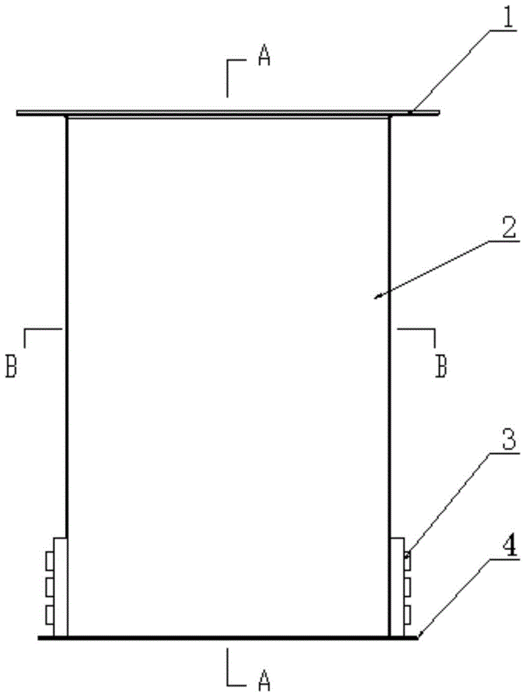
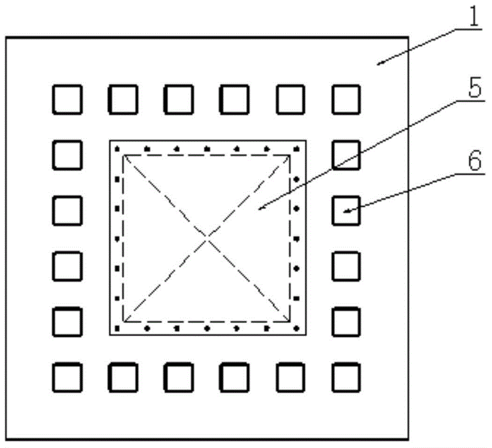
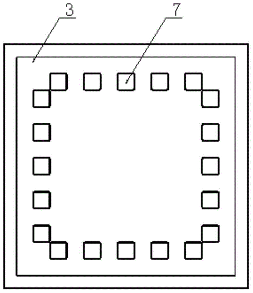
[0033] A catalytic combustion bed furnace core structure with a heater, comprising a furnace core peripheral plate 2, an upper end plate 1 fixed at its upper end and a lower end plate 4 fixed at its lower end, and a furnace core inner The coaming plate 10, the air inlet channel 9 and the air outlet channel 12 are arranged alternately between the inner coaming plate of the furnace core and the peripheral plate of the furnace core, the inlet 6 of the air inlet channel is arranged on the upper end plate, and the outlet 11 of the air inlet channel is arranged on the lower end plate Between the inner wall of the furnace core, the inlet 8 of the air outlet is arranged between the upper end plate and the inner wall of the furnace core, the outlet 7 ...


PUM


Abstract

The invention relates to a catalytic combustion bed furnace core structure with a heater. The structure comprises a furnace core outer peripheral plate as well as an upper end plate and a lower end plate which are respectively mounted on the upper end and the lower end of the furnace core outer peripheral plate; a furnace core inner peripheral plate is arranged in the furnace core outer peripheral plate; gas inlet paths and gas outlet paths are alternatively arranged between the furnace core inner peripheral plate and the furnace core outer peripheral plate; the inlet of each gas inlet path is arranged on the upper end plate; the outlet of each gas inlet path is arranged between the lower end plate and the furnace core inner peripheral plate; the inlet of each gas outlet path is arranged between the upper end plate and the furnace core inner peripheral plate; the outlet of each gas outlet path is arranged on the lower end plate; a gas guide shield with an inversed rectangular pyramid structure is arranged at the lower face of the middle of the upper end plate; the heater is arranged in the furnace core body corresponding to the outlet of each gas inlet path and is fixedly mounted on the furnace core outer peripheral plate. The catalytic combustion bed furnace structure is simple in arrangement, the heat efficiency of the furnace core body can be effectively improved, the heat loss can be reduced, the heat recovery utilization rate can be improved, the temperature in the furnace core structure can be more even during combustion, and the burning efficiency and the purifying rate are improved.

Description

technical field [0001] The invention belongs to the field of catalytic combustion beds, in particular to a catalytic combustion bed furnace core structure with a heater. Background technique [0002] The core structure of the existing catalytic combustion bed is usually made of heat-resistant steel plates or industrial kiln masonry materials, which mainly deal with industrial volatile organic pollutants that are most harmful to people's health in PM2.5. In the core structure, the air inlet and outlet are set at the upper and lower ends of the furnace core structure. Although the existing structure can realize catalytic combustion, there are the following problems: 1. The heat loss of the furnace core structure itself is large, and the heat recovery efficiency is low; 2. The furnace core The temperature in the structure is not uniform, and the temperature is generally high in the center and low in the edge, which reduces the combustion efficiency of industrial volatile organi...

Claims


Application Information

Patent Timeline
Patent Type & Authority Patents(China)
IPC IPC(8): F23G7/07F23C13/00
Inventor 朱殿兴刘光明冯正赵崇光谷德明刘迎春
Owner 赛智环保科技(天津)有限公司
Why Eureka
Try Eureka