Thermal energy recovery system containing waste hot water

A technology for heat energy recovery and waste water, which is applied in filtration circuits, heat exchange equipment, lighting and heating equipment, etc. It can solve the problems of easy blockage of filters and recovery efficiency, and achieve the effect of compact structure, reasonable design and good filtering effect

Inactive Publication Date: 2008-08-20
NANJING MASITE MACHINERY
View PDF7 Cites 0 Cited by
  • Summary
  • Abstract
  • Description
  • Claims
  • Application Information

AI Technical Summary

Problems solved by technology

[0003] The purpose of the present invention is to design a heat energy recovery system for heated waste water with no blocking of the filter device and high recovery efficiency in view of the problems of the existing hot water heat energy recovery device that the filter is easy to block and the recovery efficiency is low.

Method used


Image

  • Thermal energy recovery system containing waste hot water
  • Thermal energy recovery system containing waste hot water
  • Thermal energy recovery system containing waste hot water

Examples


Embodiment 1

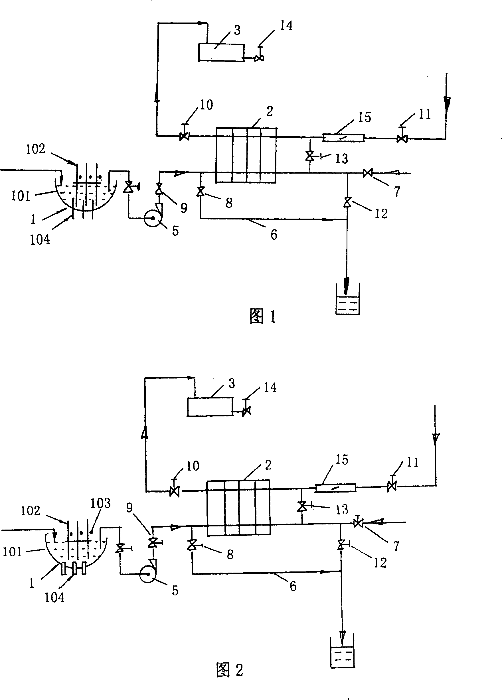
[0032] As shown in Figures 1, 6, 7, and 8.

[0033] A thermal energy recovery system for heated waste water, comprising a waste water filtering device 1, a heat exchanger 2 (a plate heat exchanger may be used, the same below), a hot water boiler 3, the water inlet end of the waste water filtering device 1 is connected to a hot sewage source, Its output is connected to the water inlet end of the hot water side of the heat exchanger 2 through the valve 15, the variable water pump 5, and the valve 9, and the water outlet end of the hot water side of the heat exchanger 2 is connected to the discharge pipe through the valve 12. A recoil steam valve 7 is installed on the pipeline between the outlet end of the hot water side of 2 and the valve 12, so as to carry out back flushing when the heat exchanger 2 is cleaned. A valve 13 for supplying clear water during cleaning is also installed on the pipeline between the water outlets on the heat source water side. In addition, in order to ...

Embodiment 2

[0036] As shown in Figures 2, 6, and 7.

[0037] A thermal energy recovery system for heated waste water, comprising a waste water filter device 1, a heat exchanger 2, and a hot water boiler 3, the water inlet end of the waste water filter device 1 is connected to a hot sewage source, and its output is through a valve 15, a variable water pump 5, and a valve 9 is connected to the water inlet end of the hot water side of the heat exchanger 2, the water outlet end of the hot water side of the heat exchanger 2 is connected to the discharge pipe through a valve 12, and the water outlet end of the hot water side of the heat exchanger 2 is connected to the valve 12 The backflush steam valve 7 is installed on the pipeline between them, so as to backwash the heat exchanger 2 when cleaning. A valve 13 for supplying clear water during cleaning is also installed. In addition, in order to protect the normal operation of the equipment during cleaning, a short-circuit discharge pipe 6 is in...

Embodiment 3

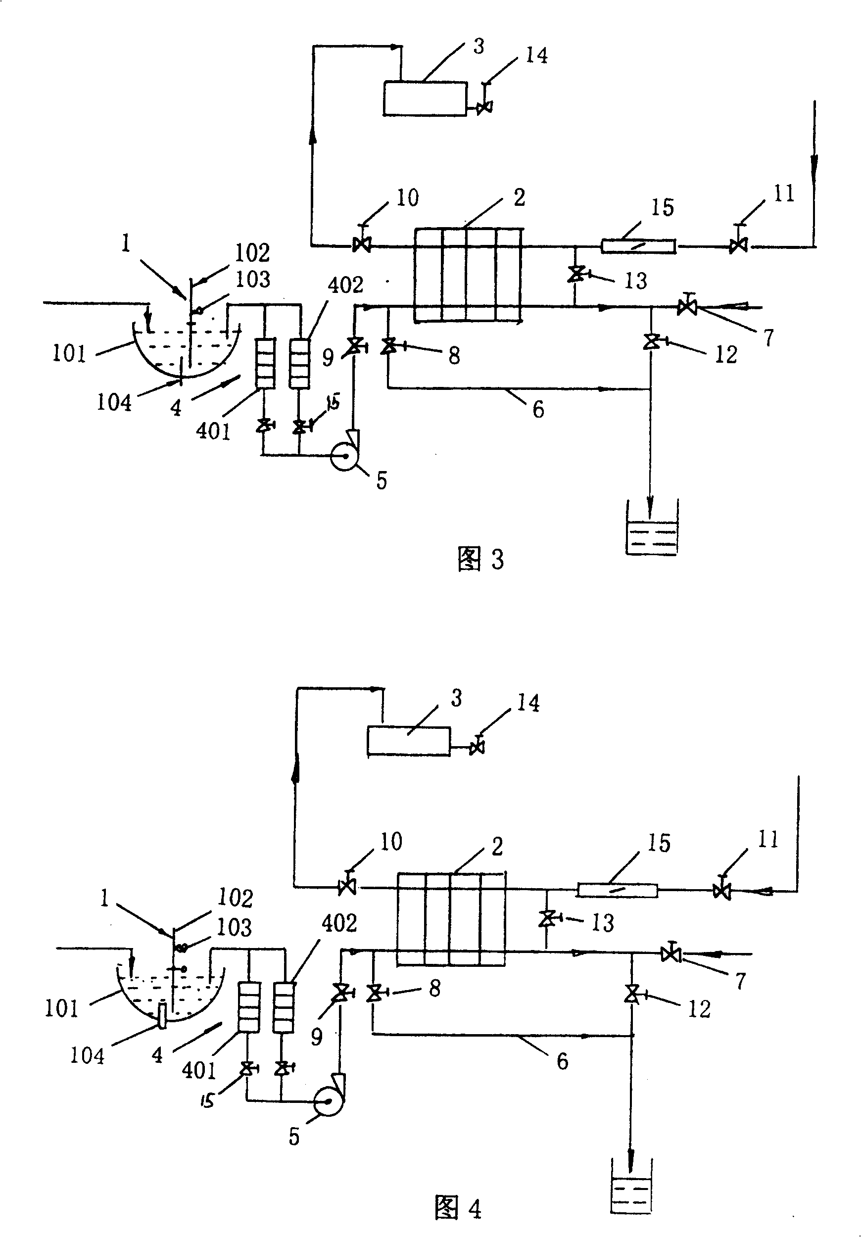
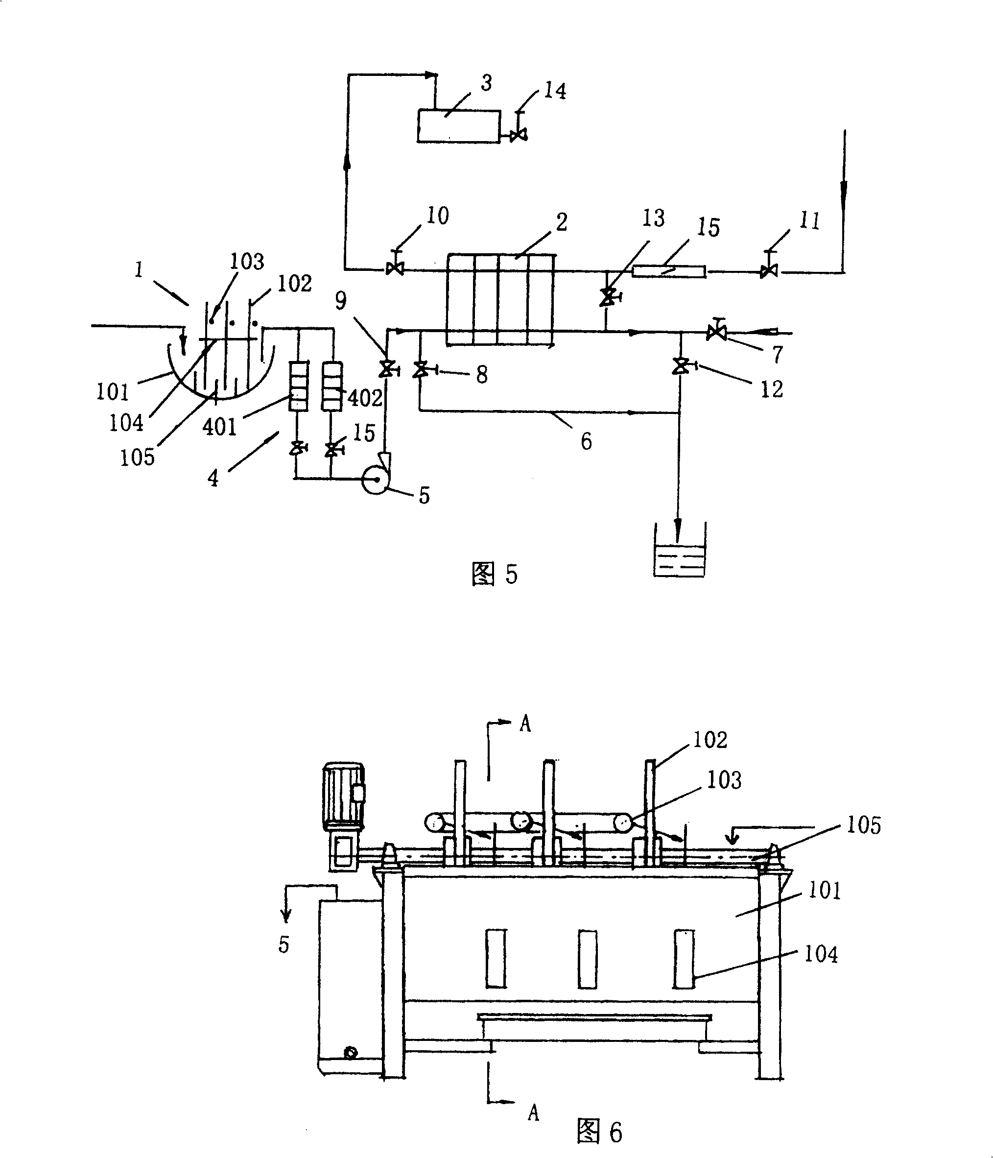
[0040] As shown in Figures 3, 6, 7, 8, 9, and 12.

[0041]A thermal energy recovery system for heated waste water, comprising a waste water filter device 1, a heat exchanger 2, and a hot water boiler 3, the water inlet end of the waste water filter device 1 is connected to a hot sewage source, and its output is through a valve 15, a variable water pump 5, and a valve 9 is connected to the water inlet end of the hot water side of the heat exchanger 2, the water outlet end of the hot water side of the heat exchanger 2 is connected to the discharge pipe through a valve 12, and the water outlet end of the hot water side of the heat exchanger 2 is connected to the valve 12 The backflush steam valve 7 is installed on the pipeline between them, so as to backwash the heat exchanger 2 when cleaning. A valve 13 for supplying clear water during cleaning is also installed. In addition, in order to protect the normal operation of the equipment during cleaning, a short-circuit discharge pip...


PUM


Abstract

The invention discloses heat energy recovery system with filtrating equipment that is not easily plugged and of high recovery efficiency against plugged easily of filter and low recovery efficiency problems of existing heat energy recover device of wastewater. It comprises wastewater filtrating equipment, heat exchanger, hot-water boiler, the inlet of wastewater filtrating equipment connects of the wastewater source, its output end connects hot-water side of heat exchanger, the heat exchanger is connected with the discharge pipe, the cold-water side of the heat exchanger is connected with cold clear water and hot-water boiler, its characteristics are the said wastewater filtrating equipment is composed of the wastewater box, at least one rotary screen filter screen, air knife, the impurity retainer, the said rotary screen filter screen is installed on the rotating shaft, air knife and the impurity retainer were installed both side of rotary screen filter screen each, feed mouth of air knife and the impurity retainer are higher than the liquid level of wastewater. It has characteristics of high efficiency and can meet the requirements of environmental protection.

Description

technical field [0001] The invention relates to a waste water treatment and waste heat recovery treatment system, especially a treatment and waste heat recovery system suitable for industrial waste water containing heat and particles or fibrous impurities discharged from papermaking, printing and dyeing, medicine, chemical industry and other chemical industries. Specifically, it is a heat recovery system for waste water containing heat. Background technique [0002] At present, the sewage discharged from industries such as textile printing and dyeing and papermaking is not only high in temperature but also contains flocculent, granular or fibrous impurities. If it is discharged directly, it will not only waste energy, but also cause serious pollution to the environment. Therefore, the market A variety of treatment equipment have appeared, but they are all of simple design, low heat recovery efficiency, simple impurity filtration, sewage discharge can not meet the requirement...

Claims


Application Information

Patent Timeline
Patent Type & Authority Patents(China)
IPC IPC(8): F28F19/01B01D36/00
Inventor 郭树绩
Owner NANJING MASITE MACHINERY
Why Eureka
Try Eureka