Water dispenser heat exchanger

A technology of heat exchangers and water dispensers, applied in heat exchange equipment, heat exchanger shells, heat exchanger types, etc., can solve the problems of difficult steam discharge, high manufacturing cost, high scrap rate, etc., and achieve high heat recovery utilization rate , long service life, good thermal conductivity

Inactive Publication Date: 2015-12-16
衢州广川电气有限公司
View PDF18 Cites 0 Cited by
  • Summary
  • Abstract
  • Description
  • Claims
  • Application Information

AI Technical Summary

Problems solved by technology

The joints of various parts in the existing water dispenser heat exchanger are generally connected by welding. At the same time, the water inlet and outlet pipes generally use three copper pipes and stainless steel pipes, and the copper pipes and stainless steel pipes also need to be sealed and isolated by welding. The structure of the water dispenser heat exchanger has high manufacturing cost, low qualified rate of finished products, high scrap rate, inconvenient installation, troublesome parts replacement, and difficult maintenance; drinking water is easily oxidized in the copper tube, which easily leads to heavy metals in the copper tube Exceeding the standard, drinking water with heavy metals exceeding the standard for a long time is not conducive to human health; at the same time, the thermal conductivity of copper pipes is not good, the heat recovery rate is not high, and the service life is not long
[0003] In addition, the pressure relief valve of a general water dispenser is installed at the lower part of the water tank. After the water in the water tank is heated, the steam is not easy to discharge, and the air pressure in the heat exchanger pipe is not easy to discharge.

Method used


Image

  • Water dispenser heat exchanger
  • Water dispenser heat exchanger

Examples


Embodiment Construction

[0024] In order to further understand the present invention, preferred embodiments of the present invention are described below in conjunction with examples, but it should be understood that these descriptions are only to further illustrate the features and advantages of the present invention, rather than limit the claims of the present invention.

[0025] The solutions in the embodiments of the present invention are clearly and completely described below in conjunction with the drawings in the embodiments of the present invention. Obviously, the described embodiments are only part of the embodiments of the present invention, not all of them. Based on the embodiments of the present invention, all other embodiments obtained by persons of ordinary skill in the art without making creative efforts belong to the protection scope of the present invention.

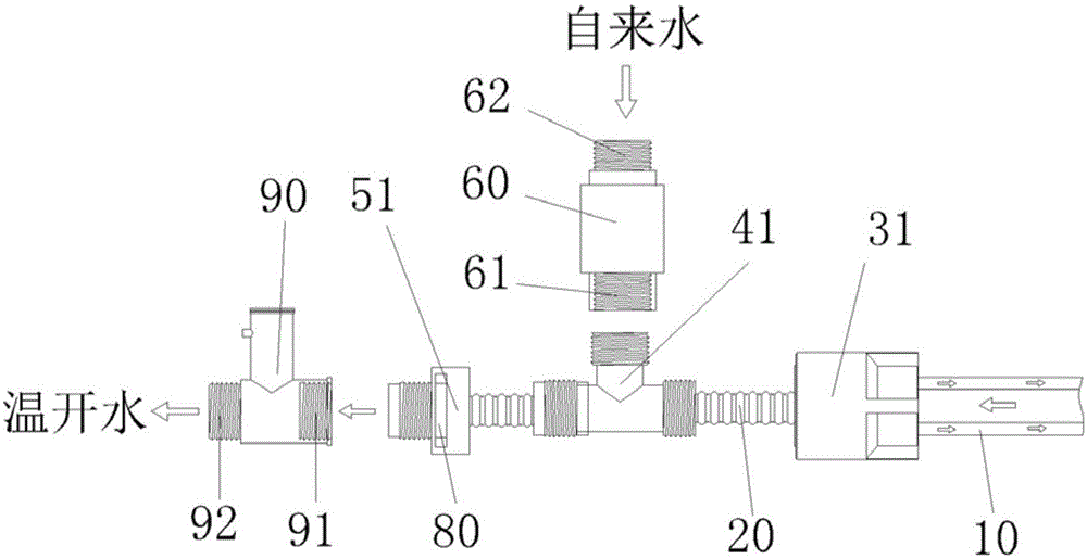
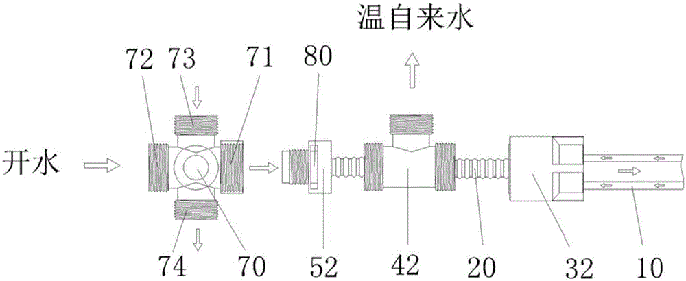
[0026] See figure 1 and figure 2 As shown, the water dispenser heat exchanger includes an outer tube 10, an inner tube 20, an...


PUM


Abstract

The invention discloses a heat exchanger of a water dispenser which comprises an outer pipe, an inner pipe arranged in the pipe cavity of the outer pipe, a first PPR inner wire straight joint and a second PPR inner wire straight joint, wherein the first PPR inner wire straight joint and the second PPR inner wire straight joint are connected at the two ends of the outer pipe respectively. One end of the first PPR inner wire straight joint is connected with a first stainless steel outer wire three joint, a first stainless steel inner and outer wire straight joint and a decompression valve in sequence, wherein the first stainless steel outer wire three joint is further connected with a check valve. One end of the second PPR inner wire straight joint is connected with a second stainless steel outer wire three joint, a second stainless steel inner and outer wire straight joint and a cross-shaped heat control valve. The inner side of the first stainless steel inner and outer wire straight joint and the inner side of the second stainless steel inner and outer wire straight joint are provided with isolation seal rings. Tap water enters from the check valve to be subjected to heat exchanging and flows back a water container, boiled water enters from the cross-shaped heat control valve to be subjected to heat exchanging, then the temperature of the boiled water is reduced, and the boiled water becomes warm water which can be drunk directly. The heat exchanger of the water dispenser is convenient to install, free of welding, low in manufacturing cost, easy to maintain, high in heat recovery utilization efficiency and long in service life.

Description

technical field [0001] The invention relates to a heat exchanger for a water dispenser. Background technique [0002] At present, heat exchangers have been widely used in the water dispenser industry. The joints of various parts in the existing water dispenser heat exchanger are generally connected by welding. At the same time, the water inlet and outlet pipes generally use three copper pipes and stainless steel pipes, and the copper pipes and stainless steel pipes also need to be sealed and isolated by welding. The structure of the water dispenser heat exchanger has high manufacturing cost, low qualified rate of finished products, high scrap rate, inconvenient installation, troublesome parts replacement, and difficult maintenance; drinking water is easily oxidized in the copper tube, which easily leads to heavy metals in the copper tube Exceeding the standard, drinking water with heavy metals exceeding the standard for a long time is not conducive to human health; at the s...

Claims


Application Information

Patent Timeline
Patent Type & Authority Patents(China)
IPC IPC(8): A47J31/44A47J31/46A47J31/58F28D7/10F28F9/26F28F21/00
Inventor 周跃亮
Owner 衢州广川电气有限公司
Why Eureka
Try Eureka