Tool rest assembly

A tool holder assembly, a pair of technology, applied in the direction of large fixed members, clamping, support, etc., can solve the problems of the tool roller bearing greatly increased life due to force, insufficient and unstable cylinder output, etc., to achieve the effect of preventing jumping

Active Publication Date: 2015-08-19
QUANZHOU HANWEI MACHINERY MFG
View PDF6 Cites 1 Cited by
  • Summary
  • Abstract
  • Description
  • Claims
  • Application Information

AI Technical Summary

Problems solved by technology

Among them, the knife rest uses a cylinder to pressurize the upper roller, and the cylinder of the knife rest on the equipment and the cylinder on the main line share the same intake pipe. In this way, the air pressure of the knife rest cylinder is unstable, and as a result, the output of the cylinder is not stable enough, resulting in In actual use, the knife roller beats under microscopic conditions
In addition, the gravity of the upper roller itself and the pressure of the cylinder are superimposed, so that according to the relationship between the action force and the reaction force, the force on the cutter roller bearing will be greatly increased and the service life will be reduced.

Method used


Image

  • Tool rest assembly
  • Tool rest assembly

Examples


Embodiment Construction

[0011] The present invention will be described in further detail below in conjunction with the accompanying drawings and specific embodiments.

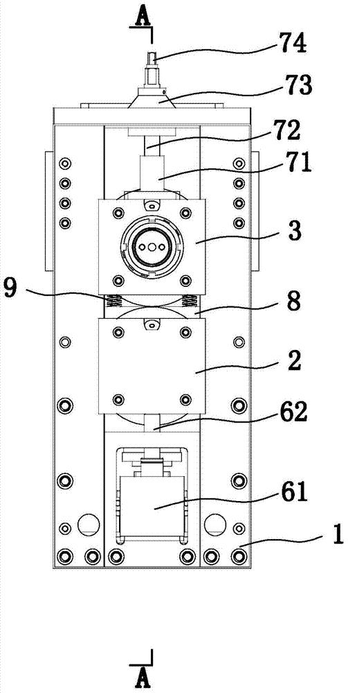
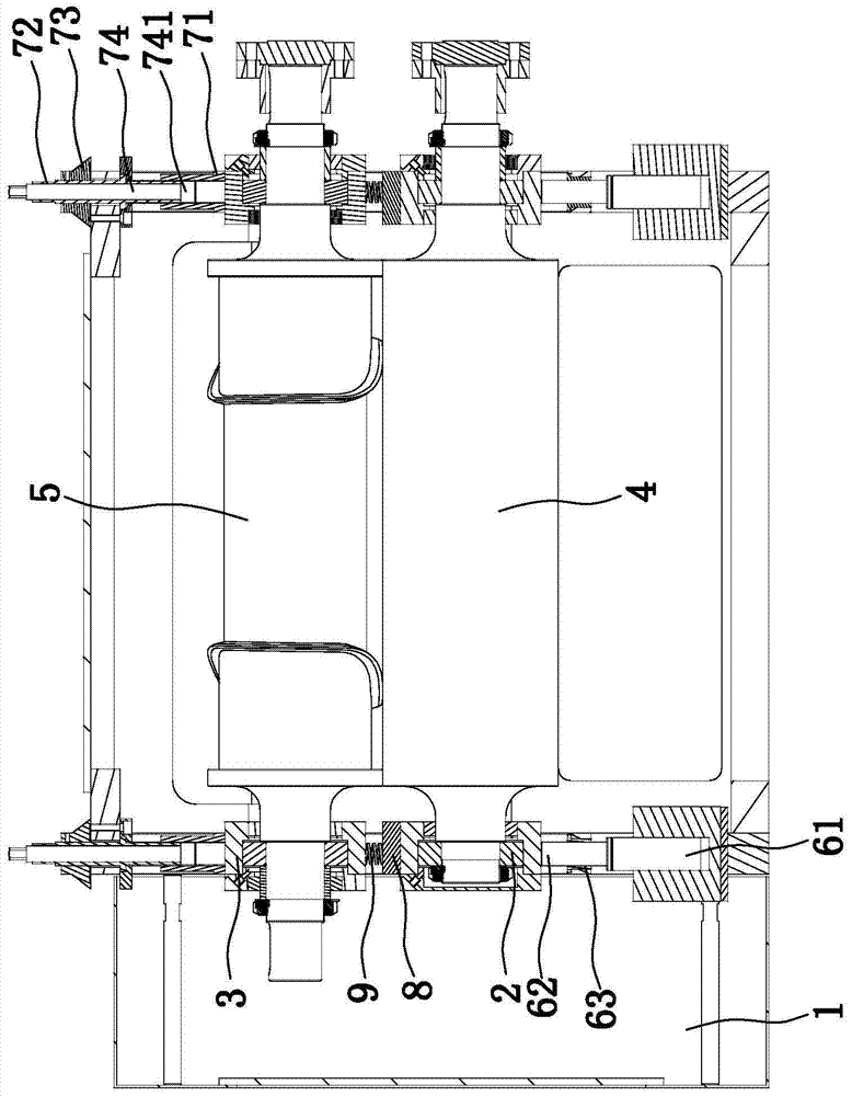
[0012] refer to figure 1 , figure 2 As shown, this embodiment provides a tool post assembly, including a frame body 1, a pair of lower sliders 2 that can slide up and down on the frame body 1, and a pair of lower sliders 2 that can slide up and down on the frame body 1. The upper slider 3, the lower roller 4 is rotatably arranged on the two lower sliders 2, the upper roller 5 is rotatably arranged on the two upper sliders 3, and the frame body 1 is located on the two lower The bottom of the slider 2 is provided with an adjustment device for adjusting the upper and lower positions of the lower slider 2, and the frame body 1 is respectively provided with a fine-tuning device for adjusting the upper and lower positions of the upper slider 3 above the two upper sliders 3. The device includes an oil cylinder 61 arranged on the frame bod...


PUM


Abstract

The invention relates to a tool rest assembly. The tool rest assembly comprises a frame body, a pair of lower slide blocks capable of vertically and glidingly arranged on the frame body, and a pair of upper slide blocks capable of vertically and glidingly arranged on the frame body; lower rollers are rotationally arranged on two lower slide blocks, and upper rollers are rotationally arranged on two upper slide blocks; adjusting devices capable of adjusting vertical positions of the lower slide blocks are respectively arranged on the frame body beneath the two slide blocks, and inching devices for adjusting vertical positions of the upper slide blocks are respectively arranged on the frame body above the two upper slide blocks; each of the adjusting devices comprises an oil cylinder on the frame body and a guide rod arranged on an oil cylinder piston rod, wherein the upper end of the guide rod is leaned and contacted with the lower ends of the lower slide blocs; a guide sleeve is arranged on the frame body, and the guide rod can be vertically and moveably arranged in the guide sleeve.

Description

technical field [0001] The invention relates to a tool rest assembly. Background technique [0002] At present, in the domestic related equipment, the general mechanism knife holder is fixed by the lower roller, and there is an adjusting inclined block between the two rollers, which is used to adjust the gap between the two knife rollers. pressure. Among them, the knife rest uses a cylinder to pressurize the upper roller, and the cylinder of the knife rest on the equipment and the cylinder on the main line share the same air intake pipe. In this way, the air pressure of the knife rest cylinder is unstable. As a result, the output of the cylinder is not stable enough, resulting in In actual use, the knife roller beats under microscopic conditions. In addition, the gravity of the upper roller itself and the pressure of the cylinder are superimposed. According to the relationship between the action force and the reaction force, the force on the cutter roller bearing will be g...

Claims


Application Information

Patent Timeline
Patent Type & Authority Applications(China)
IPC IPC(8): B23B21/00B23Q3/00
CPCB23Q1/25B23Q3/00
Inventor 林秉正陈子斌
Owner QUANZHOU HANWEI MACHINERY MFG
Why Eureka
Try Eureka