Automatic cutter disassembling device

A knife device, automatic technology, applied in the direction of positioning device, clamping, support, etc., can solve the problems of inconvenient operation, fast tool wear, and dimensional deviation of workpieces.

Active Publication Date: 2015-08-19
KEYIZHAN INTELLIGENT EQUIP CO LTD
View PDF4 Cites 15 Cited by
  • Summary
  • Abstract
  • Description
  • Claims
  • Application Information

AI Technical Summary

Problems solved by technology

[0002] CNC machine tools are frequently used in mechanical processing. The tool on the machine tool is an important part of the operation. Because of the frequent processing of hard metal products, the tool wears quickly, and the tool with a large amount of wear will cause the dimensional deviation of the workpiece during use. Therefore, it is necessary to change frequently
[0003] Existing tools are often replaced manually, and the tool is removed from the threaded handle. This replacement method is labor-intensive and inconvenient to operate; It is often tightened between them, which increases the inconvenience of manual disassembly

Method used


Image

  • Automatic cutter disassembling device
  • Automatic cutter disassembling device
  • Automatic cutter disassembling device

Examples


Embodiment Construction

[0014] The present invention will be further described in conjunction with examples, but the embodiments of the present invention are not limited thereto.

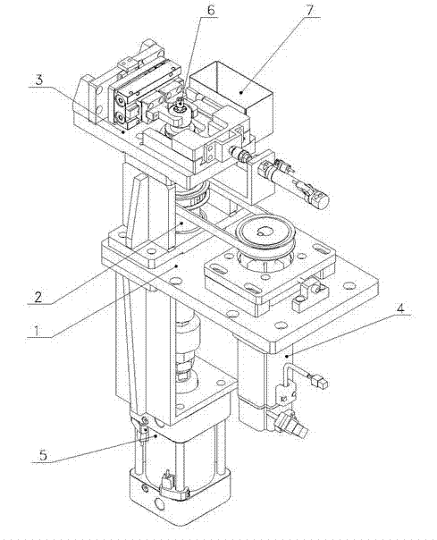
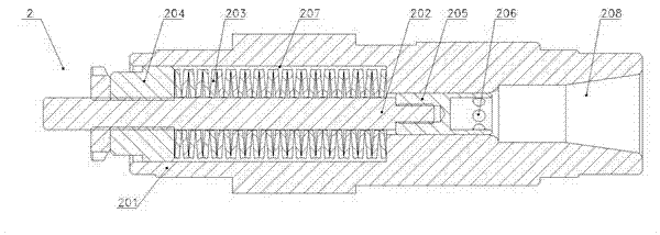
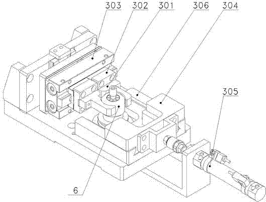
[0015] see Figures 1~5 , the present invention provides an automatic tool removal device, comprising: a fixed base plate 1, a spindle mechanism 2 perpendicular to the fixed base plate 1 and one end bearing connected to the fixed base plate 1, a tool handle clamping mechanism 3 located above the spindle mechanism 2, a control The transmission mechanism 4 for the rotation of the main shaft mechanism 2, and the jacking cylinder mechanism 5 located below the main shaft mechanism 2; The disc spring compression nut 204 threaded at the bottom, the pull claw 205 threaded with the top of the pull rod 202, the steel ball 206 positioned at the end of the pull claw 205 away from the pull rod; The connected jaw fixing block 302, the first cylinder 303 that is slidably connected with the jaw fixing block 302 and controls the opening a...


PUM


Abstract

The invention discloses an automatic cutter disassembling device, which comprises a fixed bottom plate, a main shaft mechanism, a cutter handle clamping mechanism, a transmission mechanism and a jacking cylinder mechanism, wherein the main shaft mechanism is vertical with the fixed bottom plate, one end of the main shaft mechanism is connected to the fixed bottom plate through a bearing, the cutter handle clamping mechanism is located above the main shaft mechanism, the transmission mechanism controls the main shaft mechanism to rotate, and the jacking cylinder mechanism is located below the main shaft mechanism; the main shaft mechanism comprises a main shaft, a pull rod located at an axis of the main shaft, a disc spring surrounding the pull rod, a disc spring compression nut which is in threaded connection with the lower part of the pull rod, a pulling claw which is in threaded connected with the top part of the pull rod, and a steel ball located at the end, which is away from the pull rod, of the pulling claw; the cutter handle clamping mechanism comprises a clamping claw and a first cylinder controlling the clamping claw to open or close; and the jacking cylinder mechanism is used for controlling rising of the pull rod. The automatic cutter disassembling device can loosen a cutter assembly very conveniently, realizes an automatic cutter disassembling function, and is low in labor intensity and high in efficiency. In addition, the automatic cutter disassembling device can also realize a cutter changing function. A new cutter is placed in a cutter handle, and the cutter can be clamped automatically through reversed rotation of a motor.

Description

technical field [0001] The invention relates to an automatic tool removal device, which can be used in conjunction with a manipulator to realize automatic tool removal when a large number of CNC machine tool tools are worn and need to be replaced. Background technique [0002] CNC machine tools are frequently used in mechanical processing. The tool on the machine tool is an important part of the operation. Because of the frequent processing of hard metal products, the tool wears quickly, and the tool with a large amount of wear will cause the dimensional deviation of the workpiece during use. Therefore, it is necessary to Change often. [0003] Existing tools are often replaced manually, and the tool is removed from the threaded handle. This replacement method is labor-intensive and inconvenient to operate; It is often tightened between them, which increases the inconvenience of manual disassembly. Contents of the invention [0004] The purpose of the present invention i...

Claims


Application Information

Patent Timeline
Patent Type & Authority Applications(China)
IPC IPC(8): B23Q3/155
CPCB23Q3/15513
Inventor 唐爱家朱小康郭敏郑爱华朱列辉李俊宏周四军
Owner KEYIZHAN INTELLIGENT EQUIP CO LTD
Why Eureka
Try Eureka