Hook type clamping mechanism

A technology of clamping mechanism and base, applied in the direction of workpiece clamping device, manufacturing tools, etc., can solve problems such as clamping difficulties, and achieve the effect of compact structure and small space occupation

Inactive Publication Date: 2015-08-19
WUHU MOTIONTEC AUTOMOTIVE
View PDF6 Cites 2 Cited by
  • Summary
  • Abstract
  • Description
  • Claims
  • Application Information

AI Technical Summary

Problems solved by technology

[0003] In view of the problems existing in the above-mentioned prior art, the object of the present invention is to provide a hook-type clamping mechanism with compact structure and small space occupation, through the cooperation of the hook, the rotating shaft and the driving shaft, the lin

Method used


Image

  • Hook type clamping mechanism

Examples


Example Embodiment

[0011] In order to deepen the understanding of the present invention, the present invention will be further described in detail below in conjunction with examples. The examples are only used to explain the present invention and do not constitute a limitation on the protection scope of the present invention.

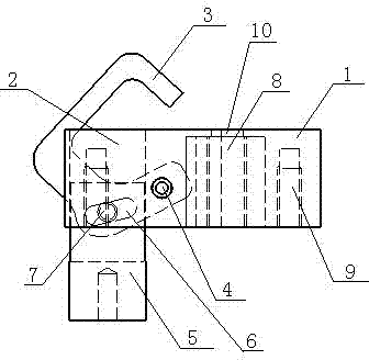
[0012] Such as figure 1 As shown, this embodiment provides a hook-type clamping mechanism, including a base 1, a through hole 2 is opened on the base 1, a hook 3 is provided in the through hole, and a rotation is provided on the base 1 Shaft 4, one end of the hook 3 is fixedly connected to the rotating shaft 4, a drive shaft 5 is arranged directly under the hook 3, the hook 3 is connected to the drive shaft 5, and the hook 3 is matched with the drive shaft 5 A waist-shaped hole 6 is provided at the position, a positioning block 7 is provided on the hook 3, and the positioning block 7 is installed in the waist-shaped hole 6, and the lower end of the driving shaft 5 is connect...


PUM


Abstract

The invention provides a hook type clamping mechanism. The hook type clamping mechanism comprises a base seat, wherein a through hole is formed in the base seat, a hook is arranged in the through hole, a rotation shaft is arranged on the base seat, one end of the hook is fixedly connected onto the rotation shaft, a drive shaft is arranged right below the hook, the hook is connected with the drive shaft, a waist-shaped hole is formed in a matching position of the hook and the drive shaft, a positioning block is arranged on the hook, the positioning block is installed in the waist-shaped hole, and the lower end of the drive shaft is connected with a drive air cylinder. The hook type clamping mechanism translates linear motion of the drive shaft into circular motion of the hook by using the hook, the rotation shaft and the drive shaft in combination, can achieve clamping motion in the vertical direction, can avoid interference possibly generated on the side face, and furthermore is compact in structure, small in occupied space, and suitable for various work environments small in space.

Description

technical field [0001] The invention relates to the field of mechanical manufacturing, in particular to a hook-type clamping mechanism with a compact structure and a small occupied space. Background technique [0002] At present, in the field of machinery manufacturing, it is very common to fix products. Whether it is processing or testing, it is necessary to fix the product before proceeding. At present, clamping clips or conventional clamping mechanisms are usually used to fix the product, and because the product Influenced by the outside line structure and the working environment, under certain circumstances, the space reserved for the product is too small, so that the clamping mechanism cannot be put in for clamping, and it can only be simply clamped from the outside, resulting in unstable fixation. Therefore, it is particularly important to solve the problem of clamping difficulties when space is insufficient. Contents of the invention [0003] In view of the problem...

Claims


Application Information

Patent Timeline
IPC IPC(8): B25B11/00
CPCB25B11/00
Inventor 周玉成汪义文许成刚马悍程
Owner WUHU MOTIONTEC AUTOMOTIVE
Why Eureka
Try Eureka