Unloading system of horizontal pneumatic powder transport vehicle

An air unloading, transport vehicle technology, applied in transportation and packaging, packaging, large containers, etc., can solve the problems of high manufacturing cost, poor manufacturability, and high residual rate, improve the longitudinal load bearing capacity, and meet the use conditions of air unloading. , The effect of reducing the weight of the car body

Active Publication Date: 2015-08-19
CRRC MEISHAN
View PDF7 Cites 8 Cited by
  • Summary
  • Abstract
  • Description
  • Claims
  • Application Information

AI Technical Summary

Problems solved by technology

At the same time, the high-pressure airflow enters the silo through the discharge port of the air chamber, and then enters the cargo compartment through the upper part of the silo through the upper air-permeable layer after passing through the material. There is a certain negative pressure difference, which causes the powder to leak into the compartment, and the dust accumulation in the compartment is not easy to clean. After the vehicle is used for a long time, a large amount of powder will accumulate in the compartment, which will affect the performance of the vehicle.
[0004] In addition, the unloading cone and air chamber at the bottom of the tank have complex structures, poor manufacturability, heavy weight, high manufacturing cost, and are unfavorable to the layout of the vehicle chassis or chassis; The pipe is in contact with it, and it is at the lowest point of the tank body. After a long time, all the moisture in the air inlet pipe will accumulate here, making the powder on the gasification plate easy to harden, and the gasification plate has poor air permeability, which directly affects the discharge effect.
Due to the characteristics of the bottom suction structure with the cone bucket and the air chamber at the bottom of the tank, it is impossible to discharge all the materials in the tank, the remaining rate is high, and the discharge speed is slow.

Method used


Image

  • Unloading system of horizontal pneumatic powder transport vehicle
  • Unloading system of horizontal pneumatic powder transport vehicle
  • Unloading system of horizontal pneumatic powder transport vehicle

Examples


Embodiment Construction

[0028] Below in conjunction with accompanying drawing, the present invention is described in detail.

[0029] In order to make the object, technical solution and advantages of the present invention clearer, the present invention will be further described in detail below in conjunction with the accompanying drawings and embodiments. It should be understood that the specific embodiments described here are only used to explain the present invention, not to limit the present invention.

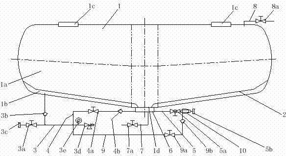
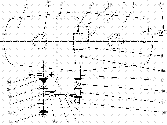
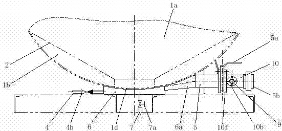
[0030] Such as figure 1 , 2 As shown in and 3, a horizontal air unloading type powder transport vehicle unloading system includes a tank body 1, a fluidized bed device 2, a main air supply pipeline system 3, a discharge air intake dredging pipeline system 4 and a discharge The pipeline system 5, the fluidized bed device 2 is arranged inside the tank body 1 and connected and fixed with the tank body 1, the tank body 1 and the upper part of the fluidized bed device 2 form a material loading compar...


PUM


Abstract

The invention discloses an unloading system of a horizontal pneumatic powder transport vehicle. The unloading system comprises a tank, a fluidized bed device, a main air supply pipeline system, an unloading air inlet dredging pipeline system and an unloading pipeline system. The fluidized bed device is arranged inside the tank and is fixedly connected with the tank, a material loading compartment which is used for loading materials is formed on the upper portions of the tank and the fluidized bed device, a tank partition compartment is formed on the lower portions of the tank and the fluidized bed device, loading holes which are communicated with the material loading compartment are formed in the upper portion of the tank, a discharge groove which is communicated with the material loading compartment is formed in the bottom of the tank, the tail end of the main air supply pipeline system penetrates the bottom of the tank and is communicated with the tank partition compartment, one end of the unloading air inlet dredging pipeline system is connected with the main air supply pipeline system, the other end of the unloading air inlet dredging pipeline system is connected with one end of the discharge groove, and the other end of the discharge groove is connected with the unloading pipeline system. The unloading system has the advantages that the materials can be pneumatically transported under high-concentration and dense-phase conditions, accordingly, purposes of increasing the unloading speeds and reducing powder remain ratios can be achieved, and the unloading system has a great potential economic benefit.

Description

technical field [0001] The invention relates to the field of bulk powder material transport vehicles, in particular to a bulk horizontal air-unloading powder material transport vehicle unloading system for powder materials and granular materials. Background technique [0002] Most of the tank trucks for bulk powder material transportation adopt a horizontal structure, and the unloading system adopts an upper suction type (upper unloading type) structure or a lower suction type (lower unloading type) structure. [0003] The bottom of the tank with the bottom suction structure generally needs to be equipped with a cone bucket and an air chamber. Under the action of self-weight, the goods are automatically unloaded to the cone bucket at the bottom of the tank. When unloading, the powder is fluidized and transported to the ash discharge pipeline by adding high-pressure air to the air chamber at the bottom of the cone bucket to realize automatic air unloading of materials. At th...

Claims


Application Information

Patent Timeline
Patent Type & Authority Applications(China)
IPC IPC(8): B65D88/28B65D88/72
CPCB65D88/28B65D88/72
Inventor 林结良李冬邓成尧刘兵李淑华
Owner CRRC MEISHAN
Why Eureka
Try Eureka