Device assembly for tensioning fork ear type stay rope or steel pull rod and tensioning construction method of device assembly

A steel tie rod and fork lug technology, applied in the field of prestressed structure construction devices, can solve problems such as unfavorable local stress control, difficulty in achieving tension control, uneven anchoring length, etc. The effect that is beneficial to the implementation of tension

Active Publication Date: 2015-08-19
LIUZHOU OVM ENG
View PDF5 Cites 11 Cited by
  • Summary
  • Abstract
  • Description
  • Claims
  • Application Information

AI Technical Summary

Problems solved by technology

In the U-shaped tooling, the left and right U-shaped load-bearing rings are unevenly anchored through the conversion box, so that the force on the left and right U-shaped load-bearing rings is uneven during the tensioning process and deflects, which is not conducive to the application of stress; On the other hand, there is no constraint between the U-shaped load-bearing rings. During the tensioning process, the U-shaped load-bearing rings deviate along the axial direction of the pin shaft, and even slip off from the outer arc surface of the lug plate, making it difficult to achieve tension control. 3. The U-shaped load-bearing ring is in line-surface contact with the arc surface of the cable or steel rod, which is not conducive to local stress control, and it is difficult to achieve when large-tonnage tensioning is involved.

Method used


Image

  • Device assembly for tensioning fork ear type stay rope or steel pull rod and tensioning construction method of device assembly
  • Device assembly for tensioning fork ear type stay rope or steel pull rod and tensioning construction method of device assembly
  • Device assembly for tensioning fork ear type stay rope or steel pull rod and tensioning construction method of device assembly

Examples


Embodiment 1

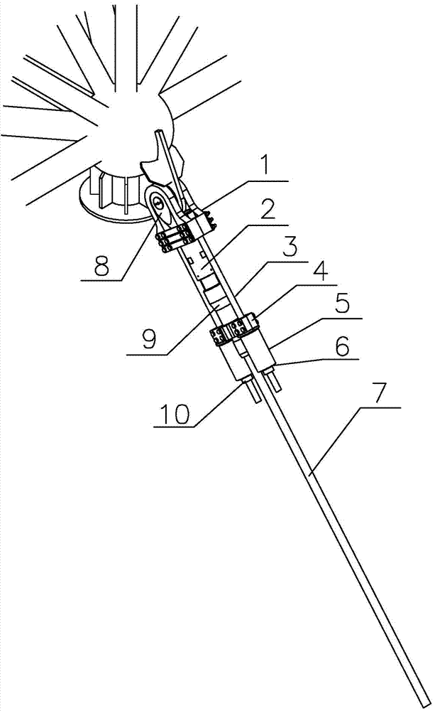
[0035] A device assembly for tensioning a fork lug type cable or a steel pull rod. The fork lug type pull cable or the fork lug steel pull rod includes a cable body or a steel pull rod 7, and is located on the cable body or the steel pull rod 7 The fork ears 8 at both ends and the adjusting tube 2 and the extension tube 9 on the near one end of the fork ears;

[0036] The device components for tensioning fork lug type cables or steel rods include: reaction frame 1, tension rod 3, pole beam 4 and jack 5 (see figure 1 );

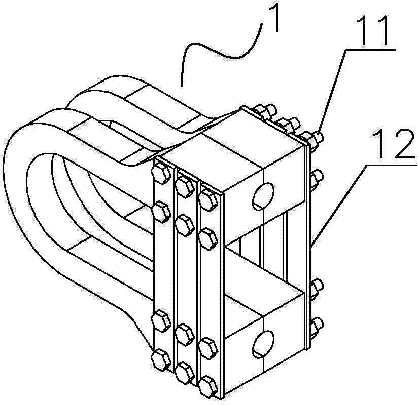
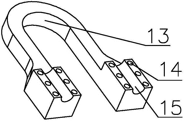
[0037] The reaction force frame 1 is similar to a "U"-shaped structure and is divided into two pieces; the inner arc size of the reaction force frame is 3-5mm larger than that of the upper end surface of the fork lug, and the opening of the "U"-shaped structure is designed to be stepped. Bolt holes 14 and semicircular grooves Ⅰ15 for the tension rod for passing through the tension rod (see diagram 2-1 , Figure 2-2 );

[0038] The pole beam 4 is a split in two halv...

Embodiment 2

[0041] A tension construction method for fork lug type cables or steel rods at both ends, which includes the following steps:

[0042] A. Install the reaction frame: Install the two halves of the reaction frame 1 on both sides of the fork lug 8 of the fork lug cable or steel rod. The inner arc 13 of the reaction frame and the outer arc surface of the fork lug 8 Contact; then through the bolt 11 and the connecting plate 12 to fix the two pieces of reaction frame 1 on the fork lug type cable or steel pull rod fork lug, two pull rod semi-circular groove I merge into a through hole;

[0043] B. Install the pole pole beam: install the pole pole beam 4 at the position of the cable body or steel tie rod 7 extension tube 9; when installing, fasten the large semicircular groove 44 of the pole pole beam on the cable body or steel tie rod, and connect the pole pole beam through bolts 41 4Fixed, two tie rod semi-circular grooves Ⅱ 43 are combined into a circular through hole for the tension ro...


PUM


Abstract

The invention provides a device assembly for tensioning a fork ear type stay rope or a steel pull rod. The device assembly comprises a counter-force rack, a tensioning rod, a carrying pole beam and a jack; the counter-force rack is of a similar U-shaped structure and divided into two pieces; the opening of the U-shaped structure is designed into a step shape, and a bolt holes and a tensioning rod semicircular groove I to allow the tensioning rod to pass through are formed in the step; the carrying pole beam is of a split two-half structure, and the stay rope or the steel pull rod is capable of passing through the middle of the split two-half structure, and tensioning rod semicircular grooves II for mounting the tensioning rod are formed on the two sides of the split two-half structure; when the device assembly is applied to tensioning construction, the two pieces of the counter-force rack are mounted on the two sides of the fork ear of the fork ear type stay rope or the steel pull rod and are integrated by use of a bolt and a connecting plate; the two-half carrying pole beam is mounted on the extension cylinder end of the fork ear type stay rope or the steel pull rod and fixed by use of a bolt; the tensioning rod is put through the carrying pole beam and the counter-force rack, and anchored by use of a fixing nut at one end of the counter-force rack; the jack and a base plate are mounted on the other end of the tensioning rod and the other end of the tensioning rod is anchored by use of a tensioning nut; the device assembly is good in safety and high in universality in tensioning construction.

Description

technical field [0001] The present invention relates to a prestressed structure construction device and its method, in particular to a device assembly for tensioning fork lug cables or steel rods and a device for tensioning fork lug cables or steel rods. Construction method. Background technique [0002] In the prestressed structure, some prestressed cable bodies or steel rods are designed as the structural form of fork lugs at both ends, and the length adjustment is realized through the adjustment cylinder on the fork lug at one end; since the anchorage is connected by the fork lug, it cannot The prestress adjustment can only be adjusted by using the conventional connection sleeve and the anchor head to adjust the prestress by tensioning in the form of a pole; but because the adjustment of the prestress tool in the form of a pole requires the cable or steel rod, the installation position must be considered in the design , the design and manufacture requirements for the cab...

Claims


Application Information

Patent Timeline
Patent Type & Authority Applications(China)
IPC IPC(8): E04G21/12
Inventor 韦福堂莫德荣张国强沈理熊佳雯
Owner LIUZHOU OVM ENG
Why Eureka
Try Eureka