Flushing water pressure control system and control method for muddy water shield machine

A pressure control and shield machine technology, applied in the field of shield machines, can solve the problems of huge fluctuations in water supply pressure and frequent start-up of booster pumps, and achieve the effects of preventing water supply pressure fluctuations, reducing the number of starts, and stabilizing the pressure

Active Publication Date: 2017-07-07
CHINA RAILWAY CONSTR HEAVY IND
View PDF7 Cites 0 Cited by
  • Summary
  • Abstract
  • Description
  • Claims
  • Application Information

AI Technical Summary

Problems solved by technology

[0006] The purpose of the present invention is to provide a flushing water pressure control system for muddy water shield machines to solve the technical problems of frequent start-up of booster pumps and huge fluctuations in water supply pressure as flushing water consumption changes

Method used


Image

  • Flushing water pressure control system and control method for muddy water shield machine
  • Flushing water pressure control system and control method for muddy water shield machine

Examples


Embodiment 1

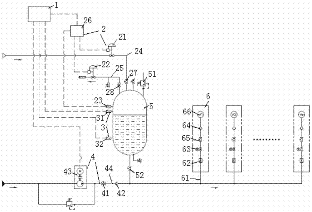
[0057] Embodiment one: if figure 1 As shown, the initial state adjustment of the system: before starting the system, set the pressure holding value of the valve controller 26 (that is, the pressure value required to be controlled by the pressure holding system) and the take-off pressure of the safety valve 51, and adjust the pressure on the terminal flushing pipeline 61. The opening of the electric ball valve 63, keep the manual ball valves 27, 28 in the closed state, the electric ball valve 63 in the closed state, and the manual ball valves 41, 65 in the open state, then start the booster pump unit 43 to start flushing the pipeline and the water tank 5 Fill water, when the liquid level in the water tank reaches the position of the high level liquid level switch 31, the liquid level switch sends a message, the PLC controller sends an instruction to stop the booster water pump unit, then opens the manual ball valve 27, 28, starts the air pressure maintaining system, the system ...

Embodiment 2

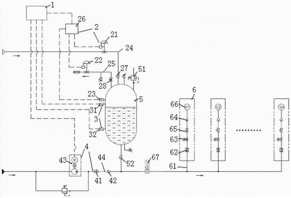
[0062] As a further improvement of the first embodiment, an electromagnetic flowmeter 67 is added to the main pipeline between the first one-way valve 42 and the terminal flushing pipeline 61 . During the working period of the pipeline system, the electromagnetic flowmeter detects the flushing water flow consumed by the main pipeline in real time and transmits it to the PLC controller 1 . In the valve flushing state, when the number of ball valves flushing at the same time is large, resulting in the instantaneous flushing water consumption exceeding the set value in the control program, the PLC controller 1 starts the booster water pump unit 43, and the water pump and the water tank work together to Plumbing system for water supply. This solution is especially suitable for the situation where there are a large number of terminal flushing pipelines 61 (such as the flushing water pipeline system on a muddy water shield with a large diameter).


PUM


Abstract

The invention provides a slurry shield tunneling machine flushing water pressure control system comprising a PLC, an air pressure maintaining system connected to the PLC through a control line, a liquid level adjusting component and a water incoming adjusting component. The air pressure maintaining system, the liquid level adjusting component and the water incoming adjusting component are connected to a water tank, and the water outlet of the water tank is connected to multiple terminals; the water outlet of the water tank and a pressurizing pump unit are connected to a terminal pipeline; a liquid level switch comprises at least two liquid level switch units located in horizontal levels of different heights; the air pressure maintaining system comprises an air incoming adjusting valve, an exhausting adjusting valve and a pressure sensor; the terminal pipeline comprises a flow meter, an electrical ball valve, an one-way valve, a manual ball valve and a terminal ball valve. According to the system, the outlet pressure of the water tank is maintained through the air pressure maintaining system, the water supply pressure of the flushing water is not affected by consumption changes, and the water supply pressure fluctuation is prevented effectively.

Description

technical field [0001] The invention relates to the technical field of shield machines, in particular to a flushing water pressure control system and control method for muddy water shield machines. Background technique [0002] Slurry shield machine is currently the most widely used shield machine in subway tunnels. It has high ground subsidence control accuracy. Its biggest feature is that the muck excavated by the cutter head is transported to the outside of the tunnel through the mud pipeline system. The mud pipeline system of the slurry shield machine is also called the circulation system, which is mainly composed of a slurry inlet pipeline, a slurry discharge pipeline, a bypass pipeline and other auxiliary pipelines. There are valves, mud pumps, detection elements, etc. arranged on the mud pipeline, among which ball valves are used the most, especially ball valves with specifications above DN200. [0003] Due to the structural characteristics of the ball valve, there i...

Claims


Application Information

Patent Timeline
Patent Type & Authority Patents(China)
IPC IPC(8): E21D9/093
CPCE21D9/06
Inventor 刘飞香程永亮唐崇茂文中保秦邦江刘学梁兴生
Owner CHINA RAILWAY CONSTR HEAVY IND
Why Eureka
Try Eureka