Anti-freeze deep well

A technology for deep wells and water layers, applied in water supply installations, drinking water installations, water supply mains, etc., can solve the problems of poor antifreeze effect and low reliability, and achieve high cost, less start-up times, and strong environmental adaptability. Effect

Inactive Publication Date: 2015-10-07
中国人民解放军总后勤部建筑工程规划设计研究院 +1
View PDF8 Cites 4 Cited by
  • Summary
  • Abstract
  • Description
  • Claims
  • Application Information

AI Technical Summary

Problems solved by technology

[0004] The problems existing in the prior art are: deep-water wells in the permafrost layer have poor antifreeze effect and low reliability

Method used


Image

  • Anti-freeze deep well
  • Anti-freeze deep well
  • Anti-freeze deep well

Examples


Embodiment Construction

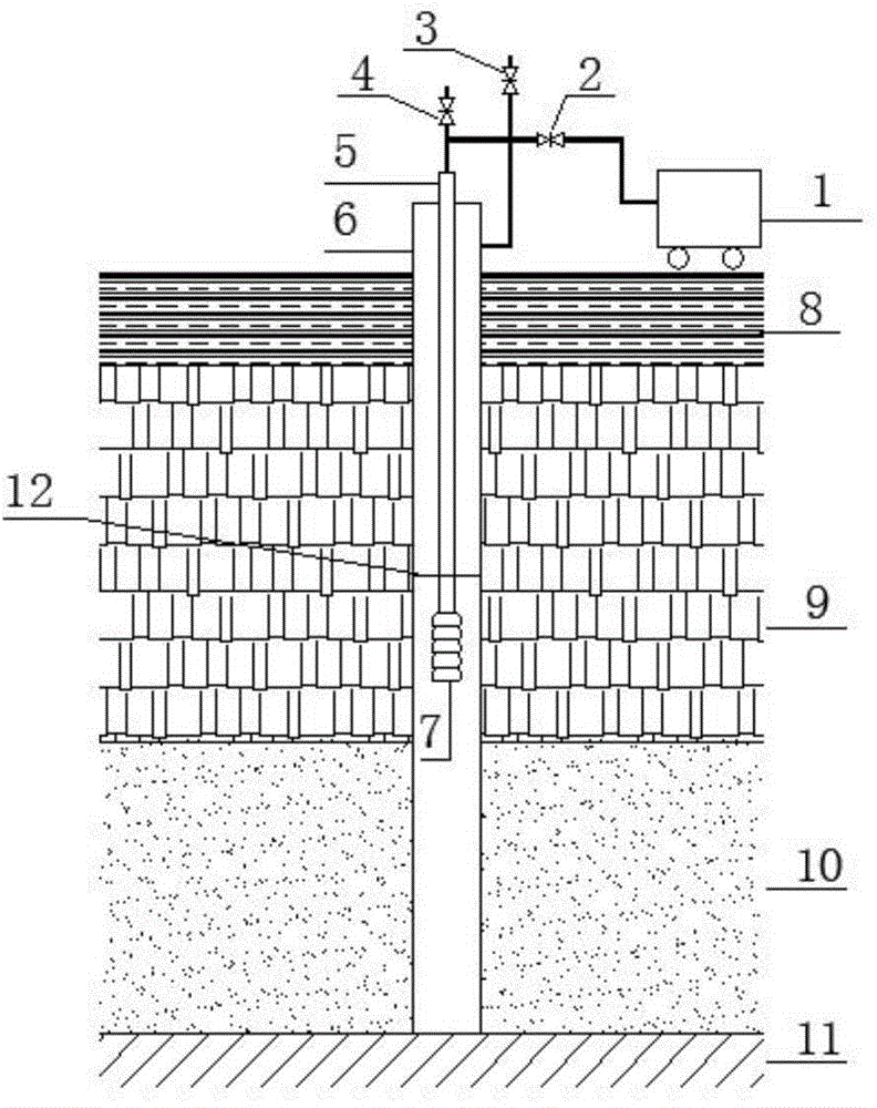
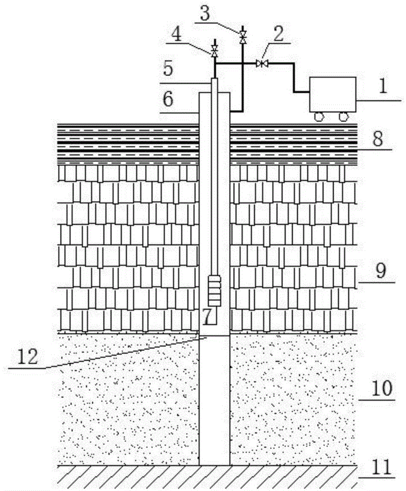
[0019] The basic principle of the antifreeze deep-water well of the present invention is: during the stoppage of the pumping device, the water level in the well is pressed below the permafrost layer by using high-pressure gas.

[0020] In order to reduce cost and use conveniently, the high-pressure gas is compressed air.

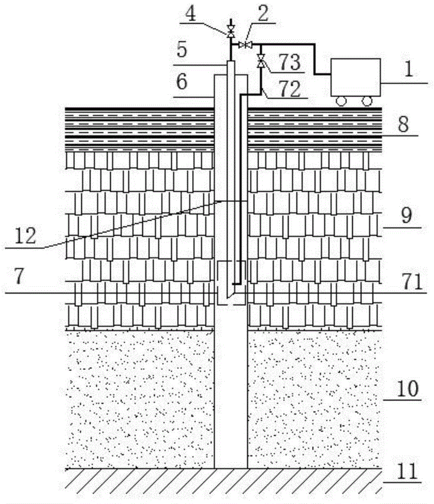
[0021] The above principles can be used in conjunction with deep well pumps or with gas extraction water devices. The implementation method of using with deep well pump is as follows:

[0022] like figure 1 As shown, the antifreeze deep-water well of the present invention realizes scheme one, comprises the borehole wall pipe 6 that passes through the permafrost layer 9 down to the aquifer, the deep well pump 7 placed in the borehole wall pipe 6, and the deep well pump 7 The water supply valve 4 communicated with the outlet of the deep well pump 7 also includes an air supply valve 2 communicated with the outlet of the deep well pump 7, and the other end of ...


PUM


Abstract

The invention discloses an anti-freeze deep well which comprises a casing pipe (6) which downwards penetrates through a perennial frozen earth layer (9) and reaches a water-bearing layer, a water pumping device (7) arranged in the casing pipe (6), a water supply valve (4) communicated with an outlet of the water pumping device (7) and an air supply valve (2) communicated with the outlet of the water pumping device (7), and the other end of the air supply valve (2) is communicated with a high pressure air source (1). By means of the anti-freeze deep well, freeze of the anti-freeze deep well in the perennial frozen earth layer can be easily and effectively prevented.

Description

technical field [0001] The invention belongs to the technical field of antifreeze water intake devices, in particular to an antifreeze deep water well with good antifreeze effect and high reliability. Background technique [0002] With the development of western my country and the needs of frontier defense construction, in some areas with high altitude, severe winter climate and harsh environmental conditions, it is necessary to open water supply wells. Some source wells need to go through permafrost (permafrost) to extract water from the aquifer below the permafrost. Most of these wells are pressurized wells, and the dynamic and static water levels of the wells will rise to the range of permafrost. When the water supply of the water pump in the well exceeds the user's water demand, the water pump will automatically stop working in order to save water resources and reduce energy consumption. When the pump stops for a long time, due to the continuous loss of heat from the w...

Claims


Application Information

Patent Timeline
Patent Type & Authority Applications(China)
IPC IPC(8): E03B3/08E03B3/15E03B7/12
CPCY02A10/30
Inventor 谢思桃丁志斌丁博文汪毅王冠军
Owner 中国人民解放军总后勤部建筑工程规划设计研究院
Why Eureka
Try Eureka