Centrifugal fan volute structure

A technology of centrifugal fan and volute, which is applied in the direction of mechanical equipment, machine/engine, liquid fuel engine, etc., to achieve the effects of good aerodynamic and noise performance, efficiency improvement, and static pressure improvement

Active Publication Date: 2015-08-19
NINGBO FOTILE KITCHEN WARE CO LTD
View PDF6 Cites 6 Cited by
  • Summary
  • Abstract
  • Description
  • Claims
  • Application Information

AI Technical Summary

Problems solved by technology

[0003] The volute structures of various centrifugal fans are also disclosed in the prior art, such as "A Centrifugal Fan for Range Hood and Its Volute" as disclosed in the Chinese invention patent No. ZL 201110118687.5 (authorized announcement No. CN 102182707 B). Shell profile line generation method", the volute includes a volute top plate, a volute bottom plate and a volute coaming, the contour line of the inner side of the volute coaming is the volute profile, and the volute profile is formed by the first straight line DE , the first arc line EF, the second arc line FG, the helix line GH, and the second straight line segment HI are smoothly transitioned and connected. Although the volute adopts the above-mentioned volute profile, it is beneficial to improve the air volume and air volume of the centrifugal fan. pressure, efficiency and reduce aerodynamic noise, but the structure of the volute still does not fully consider the non-uniformity of the inlet circumferential flow parameters and the influence of the flow field in the circumferential plane of the volute, and further improvement is needed

Method used


Image

  • Centrifugal fan volute structure
  • Centrifugal fan volute structure
  • Centrifugal fan volute structure

Examples


Embodiment Construction

[0015] The present invention will be further described in detail below in conjunction with the accompanying drawings and embodiments.

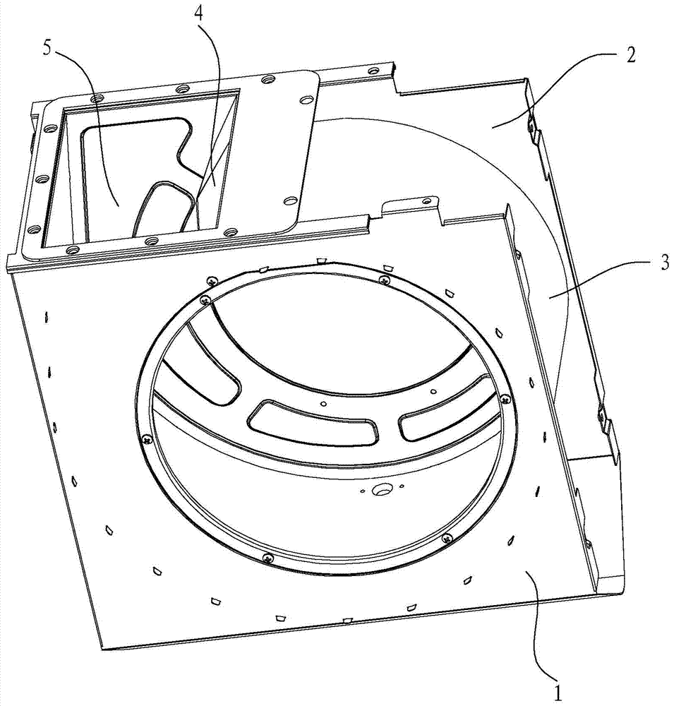
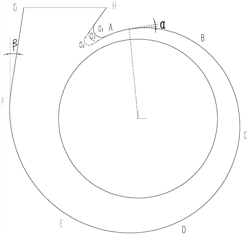
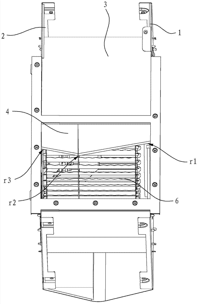
[0016] Such as Figure 1 to Figure 3 As shown, the volute structure of the centrifugal fan in this embodiment includes a volute top plate 1, a volute bottom plate 2, and a volute coaming plate 3 connected between the volute top plate 1 and the volute bottom plate 2. The volute type of the volute The lines include a start line HA and an end line FG, wherein the start line HA is located at one end of the volute line and corresponds to the volute tongue 4, and the end line FG is located at the other end of the volute line and is adjacent to the fan outlet 5.

[0017] In this embodiment, the volute-shaped line between the starting line HA and the ending line FG is a helical line. Specifically, the helix includes an initial helix AB, an intermediate helix, and an end helix EF with a smooth transition in sequence, wherein the initial helix AB is co...


PUM


Abstract

A centrifugal fan volute structure comprises a volute top plate, a volute bottom plate and a volute surrounding plate; a volute molded line comprises a starting line HA and a finishing line FG; the centrifugal fan volute structure is characterized in that the volute molded line between the starting line HA and the finishing line FG is a spiral line; the spiral line comprises a starting spiral line AB connected with the starting line HA, a finishing spiral line EF connected with the finishing line FG and a middle spiral line connected between the starting spiral line and the finishing spiral line; spiral angles of the starting spiral line AB and the finishing spiral line EF are smaller than a spiral angle of the middle spiral line. According to the centrifugal fan volute structure, the spiral line between the starting line and the finishing line is divided into the starting spiral line AB, the finishing spiral line EF and the middle spiral line, and the spiral angles of the starting spiral line AB and the finishing spiral line EF are smaller than the spiral angle of the middle spiral line, so that the designed volute structure meet the actual working conditions; the static pressure close to the starting line is improved and the efficiency close to an optimal working condition is improved, so that the pneumatic and noise performances of a fan are better.

Description

technical field [0001] The invention relates to a centrifugal fan volute structure. Background technique [0002] Centrifugal fans have been widely used in range hoods for their advantages of high suction, low noise, and compact structure. The volute is one of the core components of the centrifugal fan. Its function is to concentrate the gas leaving the impeller, export it to the outlet of the volute, and convert the dynamic pressure into static pressure. The volute structure of the existing centrifugal fan includes a volute top plate, a volute bottom plate, and a volute coaming plate connecting the volute top plate and the volute bottom plate, wherein the volute top plate and the volute bottom plate have the same profile except for the volute tongue. The traditional volute design is generally carried out according to the unary theory, and there are two assumptions, that is, assuming that the flow parameters on the inlet circumference are uniformly distributed and the flow ...

Claims


Application Information

Patent Timeline
Patent Type & Authority Applications(China)
IPC IPC(8): F04D29/42
CPCF04D29/4226
Inventor 徐鑫叶丰何立博徐群浪李斌茅忠群诸永定申志贤
Owner NINGBO FOTILE KITCHEN WARE CO LTD
Why Eureka
Try Eureka