Superconducting high-frequency testing system and method

A technology of testing system and testing method, which is applied in the direction of electronic circuit testing, measuring electricity, measuring devices, etc., can solve problems such as inconsistency of circuit working conditions, and achieve the effect of simple circuit structure

Active Publication Date: 2022-06-24
SHANGHAI INST OF MICROSYSTEM & INFORMATION TECH CHINESE ACAD OF SCI
View PDF13 Cites 0 Cited by
  • Summary
  • Abstract
  • Description
  • Claims
  • Application Information

AI Technical Summary

Problems solved by technology

[0005] In view of the above-mentioned shortcomings of the prior art, the purpose of the present invention is to provide a superconducting high-frequency testing system and method for solving the problem of inconsistency between the high-frequency test in the prior art and the actual working conditions of the circuit to be tested

Method used


Image

  • Superconducting high-frequency testing system and method
  • Superconducting high-frequency testing system and method
  • Superconducting high-frequency testing system and method

Examples


Embodiment 1

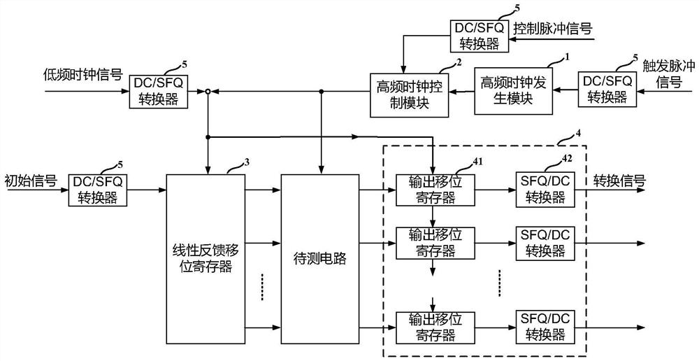
[0073] This embodiment provides a superconducting high frequency test system, the superconducting high frequency test system includes: a high frequency clock generation module 1 , a high frequency clock control module 2 , a linear feedback shift register 3 and an output conversion module 4 .

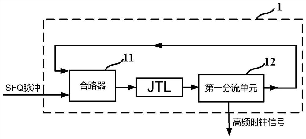
[0074] Specifically, the high-frequency clock generating module 1 is implemented based on a ring oscillator, receives a trigger pulse signal, and outputs a periodic high-frequency clock signal.

[0075] As an example, as figure 2 As shown, the high-frequency clock generation module 1 includes a combiner 11 and a first splitting unit 12; the combiner 11 receives a trigger pulse signal and a split clock signal, and outputs a combined clock signal; the first splitter The unit 12 receives the combined clock signal, and outputs two signals that are the same as the combined clock signal, one of which is output as the split clock signal, and the other is output as the high-frequency clock sign...

Embodiment 2

[0099] This embodiment provides a superconducting high-frequency test method. In this embodiment, the superconducting high-frequency test method is implemented based on the superconducting high-frequency test system of the first embodiment. In practical applications, the method can be based on any A system capable of implementing the method is performed and is not limited to this embodiment. Include the following steps:

[0100] The high-frequency clock generation module 1 receives the trigger pulse signal and outputs a periodic high-frequency clock signal;

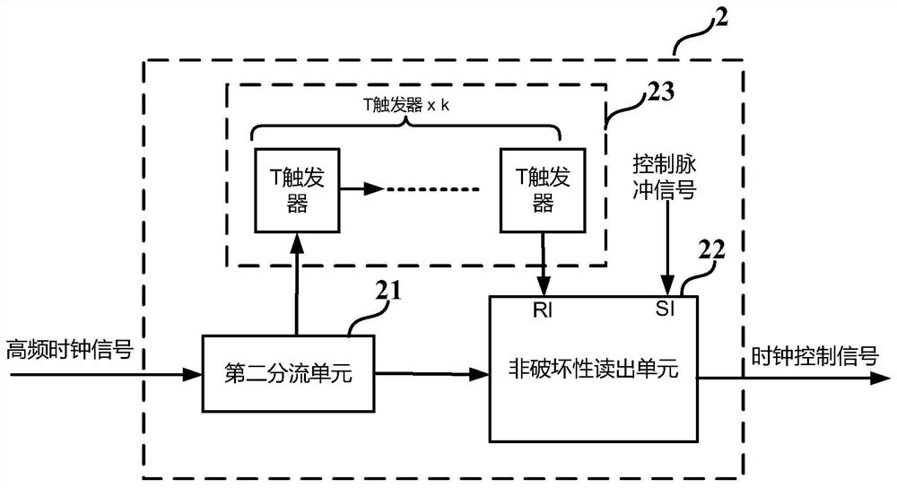
[0101] The high-frequency clock control module 2 receives the control pulse signal, controls the continuity of the high-frequency clock signal, and outputs the high-frequency control clock signal;

[0102] The linear feedback shift register 3 receives the initial signal, sets a non-zero initial state for the linear feedback shift register 3 based on the low-frequency clock signal, and simultaneously outputs the periodici...


PUM


Abstract

The present invention provides a superconducting high-frequency testing system and method, which firstly receives a trigger pulse signal, outputs a periodic high-frequency clock signal; controls the continuity of the high-frequency clock signal, and outputs a high-frequency control clock signal; receives the initial The signal is a linear feedback shift register with a non-zero initial state, and based on the high-frequency control clock signal, multiple periodic pseudo-random sequences with preset cycle lengths are simultaneously output; the circuit to be tested receives multiple pseudo-random sequences and outputs multiple test signals ; receiving the multi-channel test signal, and outputting a multiplexed signal based on a low-frequency clock signal; comparing the multiplexed signal with an expected output result to determine whether the circuit to be tested works normally. The circuit structure of the invention is relatively simple; the input signal is a pseudo-random sequence generated based on a linear feedback shift register, which can realize continuous high-frequency testing and is more in line with the actual working conditions of the circuit to be tested.

Description

technical field [0001] The invention relates to the field of superconducting circuits, in particular to a superconducting high-frequency testing system and method. Background technique [0002] Superconducting SFQ (Single Flux Quantum, Single Flux Quantum) circuit, because its speed and power consumption are both better than semiconductor CMOS circuits, it has great potential to be used in high-performance computing and other fields. Therefore, testing the high-frequency performance of the circuit is a very important step in the design of superconducting SFQ circuits, and it is also an important step to truly embody the advantages of superconducting circuits. In the design of superconducting circuits, to build a large-scale digital circuit, from the high-frequency design of each gate circuit (cell) used to the high-frequency design of each module to the high-frequency design of the entire system, it needs to be tested by actual high-frequency tests. Verification, therefore,...

Claims


Application Information

Patent Timeline
Patent Type & Authority Patents(China)
IPC IPC(8): G01R31/28
CPCG01R31/282G01R31/2832
Inventor 任洁陈理云应利良王镇
Owner SHANGHAI INST OF MICROSYSTEM & INFORMATION TECH CHINESE ACAD OF SCI
Why Eureka
Try Eureka