Pneumatic cut-off valve

A technology of pneumatic cut-off valve and air valve, which is applied in the direction of lifting valve, valve details, valve device, etc., can solve the problem that the cut-off valve occupies a large space, and achieve the effect of reducing space and reducing the lateral length

Inactive Publication Date: 2015-08-19
杨舟
View PDF5 Cites 5 Cited by
  • Summary
  • Abstract
  • Description
  • Claims
  • Application Information

AI Technical Summary

Problems solved by technology

[0005] In view of this, the object of the present invention is to provide a pneumatic shut-off valve whose structural design can effectively solve the problem that the shut-off valve occupies a large space.

Method used


Image

  • Pneumatic cut-off valve

Examples


Embodiment Construction

[0017] The embodiment of the invention discloses a pneumatic cut-off valve to solve the problems that the cut-off valve occupies a large space and the like.

[0018] The following will clearly and completely describe the technical solutions in the embodiments of the present invention with reference to the accompanying drawings in the embodiments of the present invention. Obviously, the described embodiments are only some of the embodiments of the present invention, not all of them. Based on the embodiments of the present invention, all other embodiments obtained by persons of ordinary skill in the art without making creative efforts belong to the protection scope of the present invention.

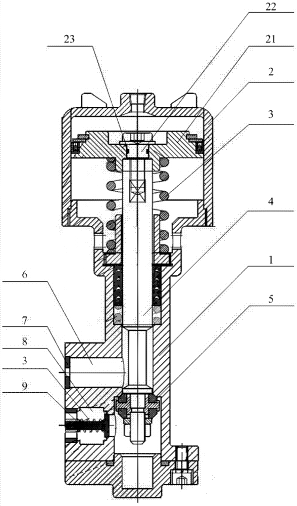
[0019] see figure 1 , figure 1 The schematic diagram of the cross-sectional structure of the pneumatic shut-off valve provided by the embodiment of the present invention. The pneumatic shut-off valve provided by the present invention includes an air valve casing 1, one end of the air valv...


PUM


Abstract

The invention discloses a pneumatic cut-off valve. The pneumatic cut-off valve comprises a gas valve shell, a cylinder piston component is arranged at one end of the gas valve shell, a valve rod is connected at one end of a piston in the cylinder piston component and is accommodated in a columnar slideway in the gas valve shell, a valve element for blocking a gas passage is arranged at the other end of the valve rod, the columnar slideway is communicated with a gas inlet passage and a gas outlet passage, a compressed spring for pushing the valve element tightly is arranged in the gas valve shell, the gas inlet passage and the gas outlet passage are arranged along the axial direction of the columnar slideway side by side vertically sequentially and are arranged on the same side of the columnar slideway, a narrow port in seal fit with the valve element is formed between the gas inlet passage and the gas outlet passage, and the compressed spring enables the valve element to butt against the narrow port. The pneumatic cut-off valve has the advantages that by the aid of the design that the gas inlet passage and the gas outlet passage are arranged side by side vertically, the gas inlet passage and the gas outlet passage are arranged on the same side of the cut-off valve which is integrally columnar, so that transverse length of a cut-off valve body is decreased greatly, and occupied space required by cut-off setting is reduced.

Description

technical field [0001] The invention relates to the technical field of valve devices, in particular to a pneumatic cut-off valve. Background technique [0002] In the process of rubber production, especially in the production of tires, it is often necessary to vulcanize rubber products. Vulcanization is a commonly used rubber processing procedure. It is a chemical reaction between rubber macromolecules and cross-linking agent sulfur under heating, and the cross-linking becomes three-dimensional. The process of network structure to achieve the purpose of converting plastic rubber into elastic rubber or hard rubber. The use of vulcanizing gas to vulcanize rubber is a commonly used technical means in the prior art. During the vulcanization process, the vulcanization temperature, humidity and the delivery volume of the vulcanizing gas need to be strictly controlled. [0003] In the passage of sulfide gas, it is often necessary to directly control the flow and on-off of sulfide ...

Claims


Application Information

Patent Timeline
IPC IPC(8): F16K1/00F16K1/52F16K27/02F16K31/122
CPCF16K1/00F16K1/52F16K27/02F16K31/1221
Inventor 杨舟
Owner 杨舟
Why Eureka
Try Eureka