
Horizontal sedimentation tank and horizontal sedimentation tank system

An advective sedimentation tank and horizontal technology, applied in the field of sedimentation tanks, can solve the problems of increasing the processing scale, large area, engineering waste, etc., and achieve the effect of reducing the horizontal speed, reducing the area and improving the sedimentation efficiency.

Pending Publication Date: 2019-03-29
BEIJING INST OF WATER
View PDF0 Cites 3 Cited by
  • Summary
  • Abstract
  • Description
  • Claims
  • Application Information

AI Technical Summary

Problems solved by technology

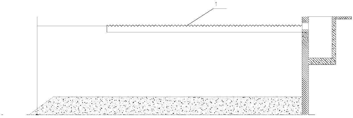
[0003] As a sedimentation tank with a long history, the advection sedimentation tank is also the sedimentation process closest to the ideal sedimentation theory. It is the most widely used in water treatment. It has a pool body, simple equipment, easy maintenance, and strong adaptability to changes in raw water quality and quantity. However, due to the characteristics of its shallow pool and large land occupation, as land resources become more and more scarce, the disadvantage of excessive land occupation has gradually become a limiting factor for its use, and it has gradually been based on water treatment in the field of water treatment. Replaced by the inclined tube (inclined plate) sedimentation tank of shallow pond theory
Inclined tube (inclined plate) sedimentation tank improves efficiency by reducing the distance of sludge settlement by layering. It is widely used in projects with tight land use. However, due to the existence of inclined tube area, the sludge in the tube needs to be washed regularly with high-pressure water. Problems such as incomplete mud discharge and easy silting have always been the biggest trouble in operation
In most of the renovation projects of water plants, in order to reduce land occupation and increase the scale of treatment, the existing advection sedimentation tanks are demolished, resulting in huge waste of the project

Method used


Image

  • Horizontal sedimentation tank and horizontal sedimentation tank system
  • Horizontal sedimentation tank and horizontal sedimentation tank system
  • Horizontal sedimentation tank and horizontal sedimentation tank system

Examples


Embodiment Construction

[0026] The specific implementation manners of the embodiments of the present invention will be described in detail below with reference to the accompanying drawings. It should be understood that the specific implementations described here are only used to illustrate and explain the embodiments of the present invention, and are not used to limit the embodiments of the present invention.

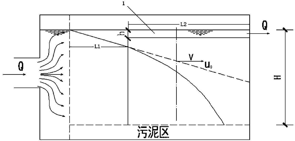
[0027] figure 1 It is a schematic diagram of an ideal advection sedimentation tank. Such as figure 1 As shown, the trajectory of the particles entering from point A is the vector sum of the horizontal flow rate and the sedimentation particle settling velocity. There must be particles of a certain size in these particles, and the settling velocity is u 0 , Just can sink to the bottom of the pool.

[0028] among them,

[0029] Where: u 0 Is the critical particle sedimentation velocity, in m / s;

[0030] Q is the water flow of advection sedimentation tank, unit m 3 / s;

[0031] A is the water surface are...


PUM


Abstract

The invention provides a horizontal sedimentation tank and a horizontal sedimentation tank system, which belong to the field of the sedimentation tank. The horizontal sedimentation tank contains waterand has a water outlet, the horizontal sedimentation tank includes: a water collecting groove connected with a water outlet, and partially disposed under the water surface of the horizontal sedimentation tank for water collection during flowing of water in the horizontal sedimentation tank and water discharge through the water outlet, so that the horizontal length of a sedimentation path of the precipitated particles can be shortened. The horizontal sedimentation tank and the horizontal sedimentation tank system can improve the sedimentation efficiency and reduce the land occupation area required for sedimentation of the sedimentation tank.

Description

Technical field [0001] The invention relates to a sedimentation tank, in particular to a flat flow sedimentation tank and a flat flow sedimentation tank system. Background technique [0002] Sedimentation is a process in which suspended particles in water are separated from water by gravity. The precipitation process is an important part of the conventional water treatment process. It is essential in municipal water supply and sewage treatment. It is also a process that occupies a large proportion of land and investment in water plant projects. The sedimentation tanks used in water treatment include advection sedimentation tanks, radial flow sedimentation tanks, vertical flow sedimentation tanks, inclined tube sedimentation tanks and various high-efficiency sedimentation tanks introduced from abroad based on the deformation of the clarification process. Advection sedimentation tanks are the most used sedimentation tanks in water purification plants and sewage plants. [0003] As ...

Claims


Application Information

Patent Timeline
IPC IPC(8): B01D21/00B01D21/04B01D21/18B01D21/24
CPCB01D21/0087B01D21/04B01D21/18B01D21/2444
Inventor 任向锋姚宁谢正威张玉龙王筱菊刘亮
Owner BEIJING INST OF WATER
Learn More