Steering apparatus

a technology of steering apparatus and sleeve, which is applied in the direction of electrical steering, steering linkages, transportation and packaging, etc., can solve the problems of limited length (length in the lateral direction) of the rack shaft, gap formed between seal members, etc., and achieve the effect of changing the air pressure in the spa

Active Publication Date: 2017-07-20
TOYOTA JIDOSHA KK +1
View PDF2 Cites 3 Cited by
  • Summary
  • Abstract
  • Description
  • Claims
  • Application Information

AI Technical Summary

Benefits of technology

[0047]If the air pressure in the space between seal members sharply decreases when the rack shaft slides, air and / or water outside of the first seal member and the second seal member are easily sucked into the space between seal members via a space between the first seal member and the first inner peripheral portion and a space between the second seal member and the second outer peripheral portion.
[0048]When the present invention is configured as described above, however, the volume V1 becomes smaller compared with the case where the outer diameter of a portion of the rack shaft, on which the screw groove is formed, is equal to or less than that of a portion of the rack shaft, on which the first outer peripheral portion is formed. Therefore, the amount of change V1 of volume V1 along with the sliding motion of the rack shaft becomes also small. Therefore, change ratio of air pressure in the space between seal members becomes small when the rack shaft slides. Therefore, when the rack shaft slides in a direction in which the air pressure of the space between seal members is decreased, there is a low possibility that air and / or water outside of the first seal member and the second seal member are sucked into the space between seal members via a space between the first seal member and the first inner peripheral portion and a space between the second seal member and the second outer peripheral portion.

Problems solved by technology

If there are irregularities on a portion (the first outer peripheral portion and the second outer peripheral portion) of the rack shaft, with which the first seal member and the second seal member come into contact respectively, there is a fear that a gap is formed between seal members (the first seal member and the second seal member) and the rack shaft, and water passes through the gap and heads to the ball screw nut.
Furthermore, the entire length (length in the lateral direction) of the rack shaft is limited by the vehicle width of the vehicle in which the steering apparatus is installed.

Method used


Image

  • Steering apparatus
  • Steering apparatus
  • Steering apparatus

Examples


Embodiment Construction

[0064]A steering apparatus according to an embodiment of the present invention will be described hereinafter with reference to the accompanying drawings.

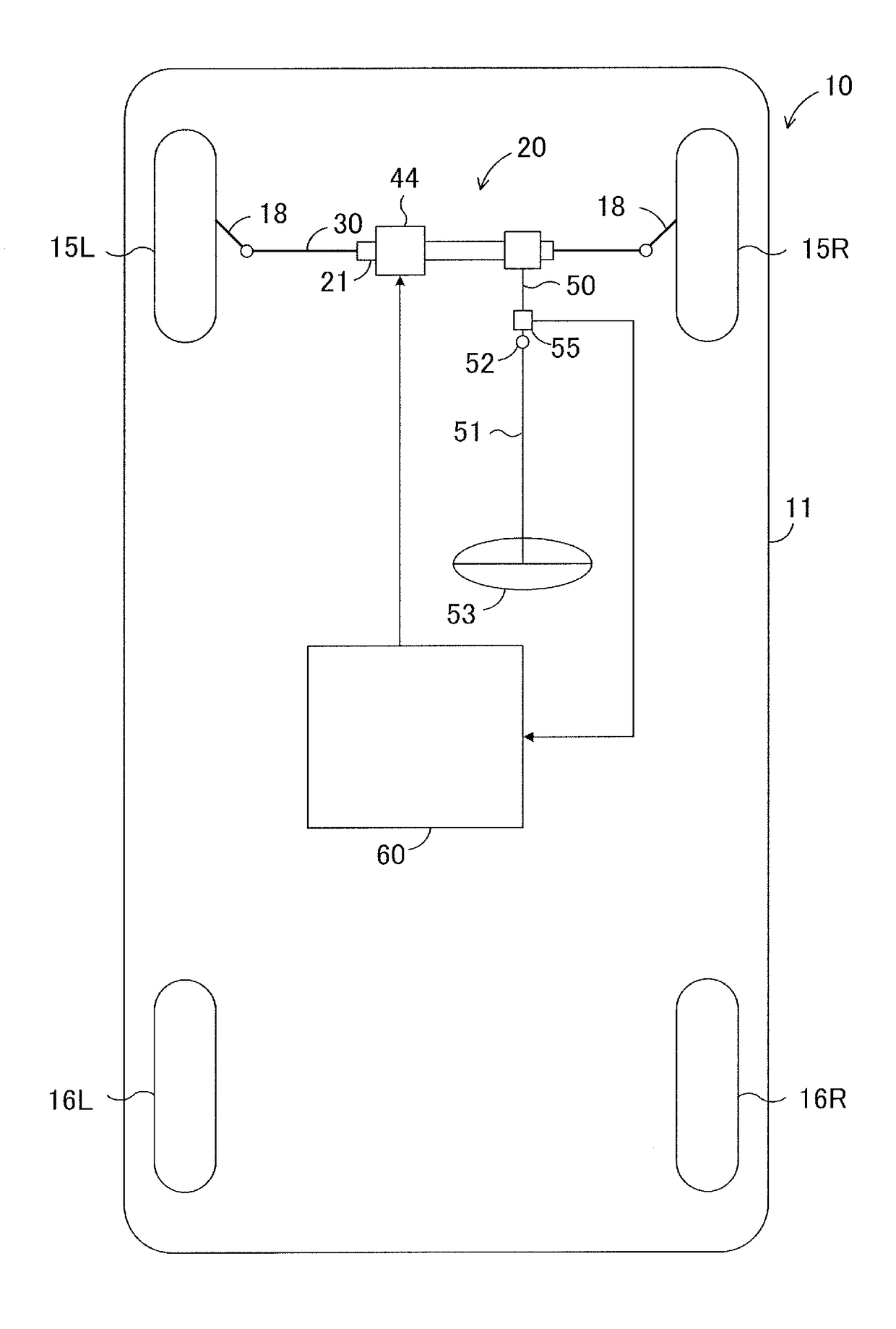
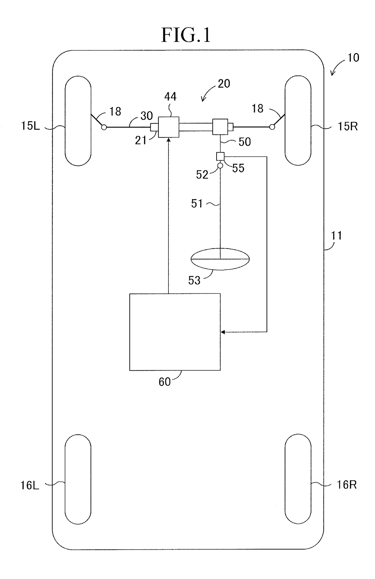
[0065]First, the overall structure of a vehicle 10 having the steering apparatus will be briefly described with reference to FIG. 1.

[0066]A vehicle body 11 of the vehicle 10 is provided in a front portion thereof with a suspension (not shown).

[0067]As is well known, the suspension is provide, as main components, with a suspension member, an upper arm, a lower arm, a carrier, a coil spring, and a shock absorber.

[0068]A left carrier (knuckle arm) is supported by distal end portions of the left upper arm and the left lower arm, while a right carrier is supported by distal end portions of the right upper arm and the right lower arm. Each of the carriers can rotate about a king pin shaft. The left and right carriers support a front wheel 15L and a front wheel 15R respectively so that the front wheel 15L and the front wheel 15R can rotate...


PUM


Abstract

The steering apparatus includes a first seal member and a second seal member. The first seal member is fixed to one of an outer peripheral surface of a rack shaft and an inner peripheral surface of a housing. The first seal member slidably contacts with a cylindrical surface which is centered on the axis and is provided on the other of the outer peripheral surface of the rack shaft and the inner peripheral surface of the housing. The second seal member is fixed to the other of the outer peripheral surface and the inner peripheral surface. The second seal member slidably contacts with a cylindrical surface which is centered on the axis and is provided on the one of the outer peripheral surface of the rack shaft and the inner peripheral surface of the housing.

Description

BACKGROUND OF THE INVENTION[0001]1. Field of the Invention[0002]The present invention relates to a steering apparatus which performs steering assist by using a driving force of an electric motor.[0003]2. Description of the Related Art[0004]FIG. 7 is an example of a steering apparatus provided in a vehicle.[0005]The steering apparatus includes a cylindrical housing which is fixed to the front portion of the bottom of a vehicle body. The housing extends in a lateral direction, which is a width direction of the vehicle body, and the both ends thereof are opened.[0006]A rack shaft is inserted into the housing so that the rack shaft is movable in the lateral direction and is not rotatable about its own axis. The left and right ends of the rack shaft are connected to left and right front wheels via tie rods, respectively. A screw groove and a rack tooth portion are formed on two parts of the outer peripheral surface of the rack shaft respectively so that the screw groove and the rack toot...

Claims


Application Information

Patent Timeline
Patent Type & Authority Applications(United States)
IPC IPC(8): B62D5/04B62D6/10B62D3/12
CPCB62D5/0403B62D5/0463B62D6/10B62D3/12B62D5/0421B62D5/0448B62D5/22
Inventor YAMASHITA, MASAHARUKATO, HIDEYAUMETANI, AKIHISATSUKAGOSHI, MASAYUKI
Owner TOYOTA JIDOSHA KK
Why Eureka
Try Eureka