Arrangement structure for air-conditioning compressor in hybrid electric vehicle

a hybrid electric vehicle and arrangement structure technology, applied in vehicle heating/cooling devices, transportation and packaging, propulsion parts, etc., can solve the problem of engine stopping sometimes, and achieve the effect of reducing the number of components, preventing vibration of the air-conditioning compressor from being transmitted, and reducing the length of the device including the motor

Active Publication Date: 2013-11-21
SUZUKI MOTOR CORP
View PDF7 Cites 3 Cited by
  • Summary
  • Abstract
  • Description
  • Claims
  • Application Information

AI Technical Summary

Benefits of technology

[0022]In accordance with the embodiment of the present invention described above, the air-conditioning compressor is arranged and fixed on the side portion of the power generating motor or the driving motor. Accordingly, a mounting surface for the air-conditioning compressor can be easily ensured, and the air-conditioning compressor can be reasonably arranged within the engine room. Moreover, since the air-conditioning compressor generates a vibration, the air-conditioning compressor formerly needed to be mounted to a vehicle body via an elastic member. However, in the present embodiment, the air-conditioning compressor is fixed on the side portion of the power generating motor or the driving motor that is mounted to the vehicle body via an elastic member, and accordingly, the elastic member exclusively for the air-conditioning compressor becomes unnecessary and the number of components can be reduced while the vibration of the air-conditioning compressor is prevented from being transmitted to other components.
[0023]In accordance with the preferred embodiment described above, the power generating motor and the driving motor are also provided in parallel with each other in the vehicle longitudinal direction. Thus, a lateral length of a device including the motors can be shortened, and an arrangement space for the air-conditioning compressor can be easily ensured within the engine room. In addition, since the air-conditioning compressor is fixed on the side portion of the one of the motor cases, high accuracy can be ensured for a mounting surface (a side surface of the one of the motor cases) as compared to a mounting surface formed across two components. Consequently, the air-conditioning compressor that generates a vibration can be reliably mounted with high rigidity.
[0024]Since the one of the motor cases on which the air-conditioning compressor is fixed is arranged at a position behind and higher than the another one of the motor cases, the air-conditioning compressor can be arranged at a position unlikely to be damaged by deformation of the vehicle due to an impact load applied from a front side. The air-conditioning compressor can be thereby effectively protected from impacts. Since the air-conditioning compressor can be arranged at a higher position, gravel or water splashed by the running vehicle is blocked from reaching the air-conditioning compressor, thereby improving durability of the air-conditioning compressor.
[0025]Furthermore, since the air-conditioning compressor is not fixed on the side portion of the motor case of the power generating motor coupled to the engine, but is fixed to the motor case of the driving motor arranged behind the power generating motor, the air-conditioning compressor is positioned apart from a mount for the engine or the like, and the arrangement or shape of the mount is made free from restriction. The mount for the engine or the like can be thereby arranged at an optimum position.

Problems solved by technology

In the hybrid electric vehicle, however, the engine is sometimes stopped.
Accordingly, even when a mounting leg portion is broken with an electric compressor receiving a load from a side member in a vehicle crash, the projection portion comes into interference with the engine before an inverter device to stop movement of the electric compressor.

Method used


Image

  • Arrangement structure for air-conditioning compressor in hybrid electric vehicle
  • Arrangement structure for air-conditioning compressor in hybrid electric vehicle
  • Arrangement structure for air-conditioning compressor in hybrid electric vehicle

Examples


embodiment

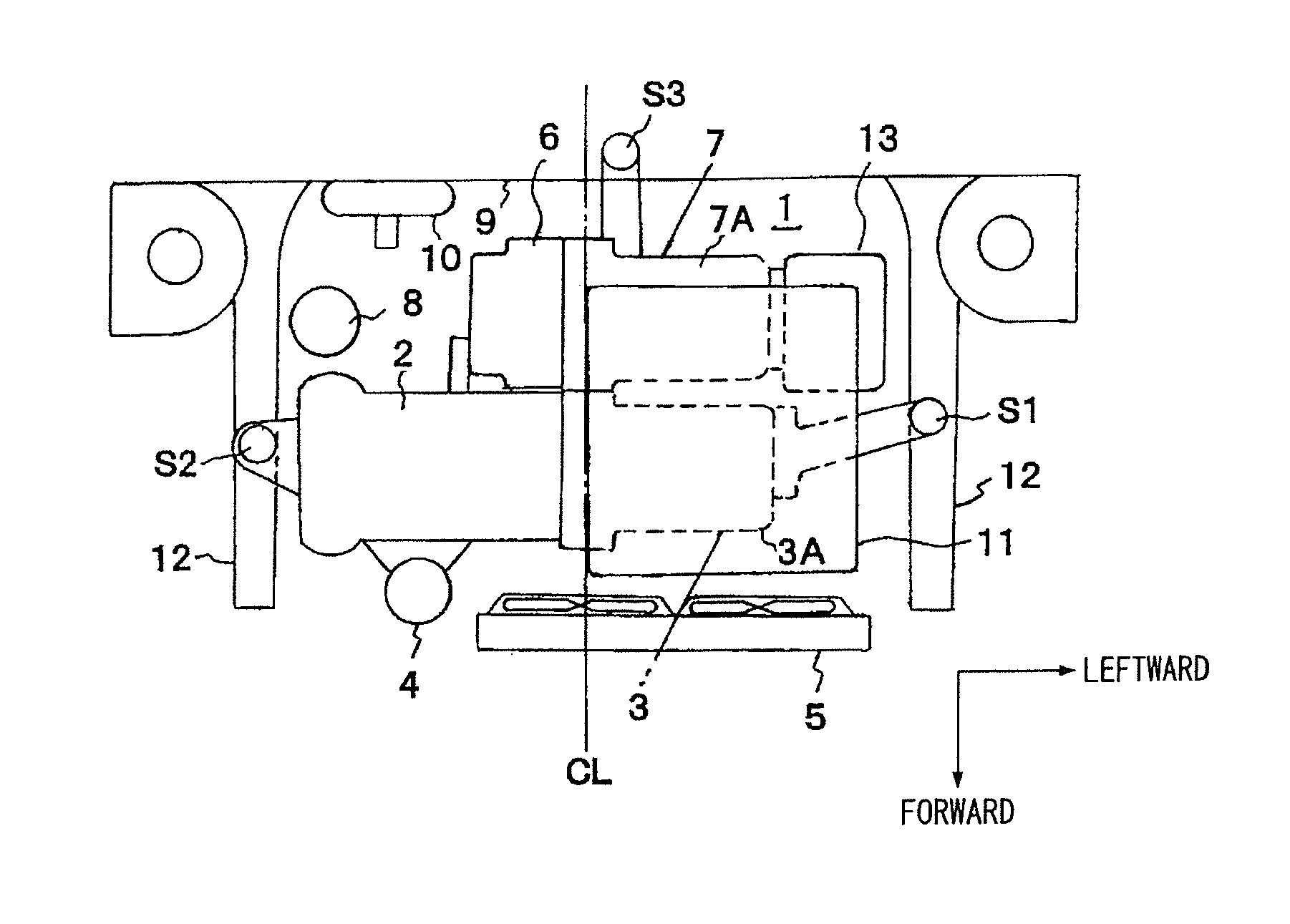
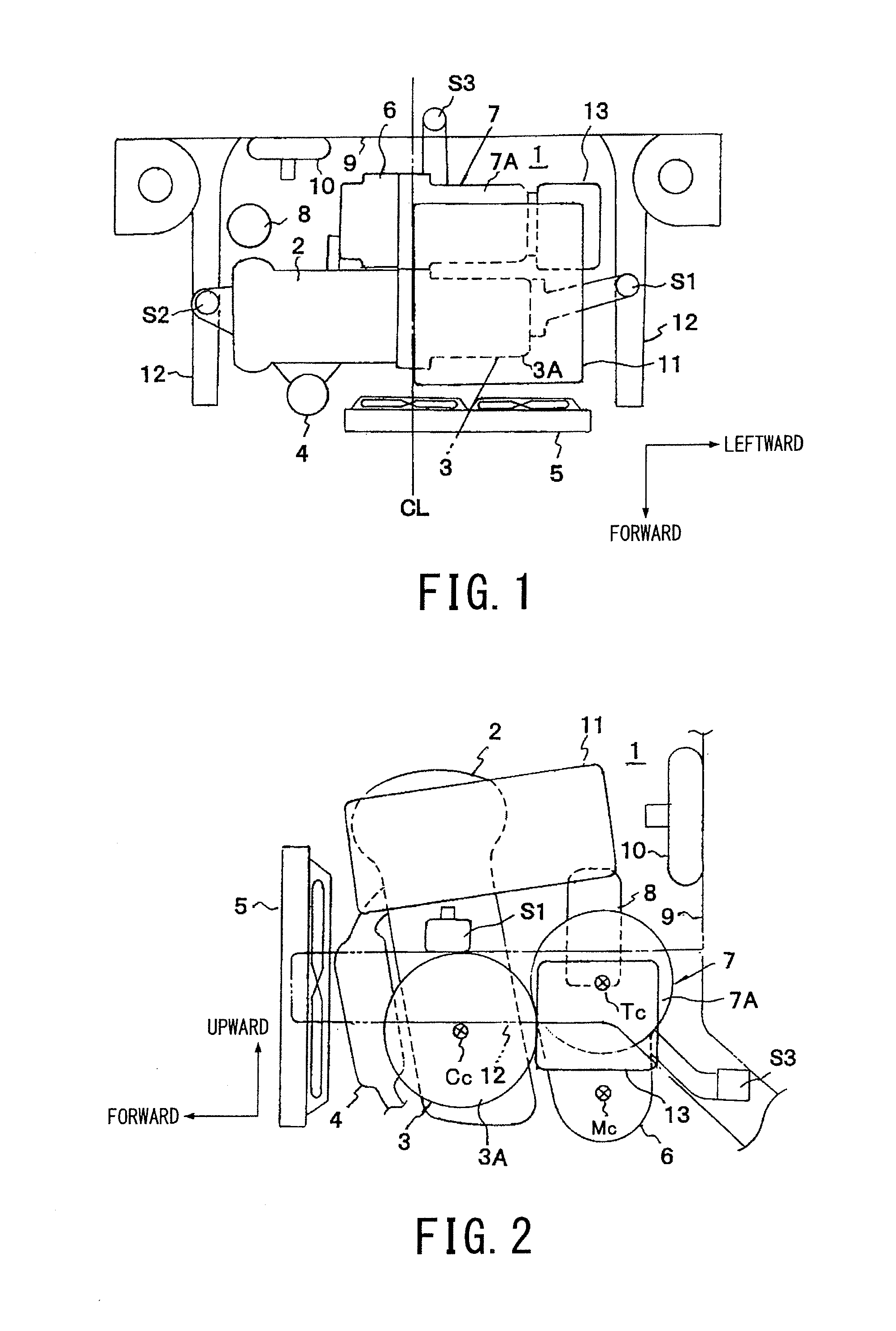
[0033]The present embodiment is applied to a hybrid electric vehicle (HEV) that employs a series system. As shown in FIG. 1, an engine 2 and a power generating motor 3 are arranged in series and coupled together in a vehicle width direction within an engine room 1 of a vehicle that employs a series system.

[0034]To be more specific, the engine 2 is arranged on a right side (a left side in FIG. 1) of the vehicle with respect to a vehicle widthwise center line CL. The power generating motor 3 is arranged in series therewith on a left side thereof. An exhaust pipe 4 is connected to a front side of the engine 2 (a lower side in FIG. 1) so as to extend from the engine 2. A radiator 5 that cools the engine 2 and an inverter 11 is arranged toward the left side ahead of the power generating motor 3 so as not to be affected by heat from the exhaust pipe 4.

[0035]A driving motor 7 that drives the vehicle and a transmission 6 that amplifies a driving force generated by the driving motor 7 and tr...


PUM


Abstract

In an arrangement structure for an air-conditioning compressor in a hybrid electric vehicle, an engine, a power generating motor, a driving motor, and an air-conditioning compressor are disposed in an engine room, the engine and the power generating motor being arranged in series, in which the air-conditioning compressor is arranged on a side portion of the power generating motor. The power generating motor and the driving motor are provided in parallel with each other in a vehicle longitudinal direction and are accommodated respectively in separate motor cases, and one of the motor cases on which the air-conditioning compressor is fixed is arranged at a position behind and higher than another one of the motor cases.

Description

Priority Claim[0001]This patent application is a U.S. National Phase of International Patent Application No. PCT / JP2011 / 053722, filed 21 Feb. 2011, the disclosure of which is incorporated herein by reference in its entirety.TECHNICAL FIELD[0002]The present invention relates to an arrangement structure for an air-conditioning compressor in a hybrid electric vehicle (HEV) that employs a series system.BACKGROUND ART[0003]FIGS. 5 and 6 show a layout example of various equipments or devices within an engine room of a conventional vehicle that runs by using only power of a vehicle engine as a driving force.[0004]FIG. 5 is a partial plan view illustrating a layout example of various devices within an engine room of a conventional vehicle. FIG. 6 is a partial side view thereof. As shown in these figures, in the conventional vehicle, an engine 102 is arranged on a right side of the vehicle with respect to a vehicle widthwise center line CL of an engine room 101. A transmission 106 is arrang...

Claims


Application Information

Patent Timeline
Patent Type & Authority Applications(United States)
IPC IPC(8): B60H1/32
CPCB60H1/3223B60H1/3229B60K6/40Y02T10/70
Inventor MOCHIZUKI, YOSHIHITO
Owner SUZUKI MOTOR CORP
Why Eureka
Try Eureka