
Closing device for steam pipe

A closed device and steam pipeline technology, applied in the direction of pipes/pipe joints/fittings, adjustable connections, passing components, etc., can solve the problems of reduced heat preservation effect, large relative displacement, poor effect, etc., to improve service life and improve The effect of reliability and easy installation

Active Publication Date: 2015-08-19
CHINA DALIAN KEHUA HEATING PIPE
View PDF6 Cites 0 Cited by
  • Summary
  • Abstract
  • Description
  • Claims
  • Application Information

AI Technical Summary

Problems solved by technology

[0002] At present, in order to avoid the reduction or even failure of the insulation layer caused by water inflow between the working pipe and the outer protection pipe of the steam pipeline, the insulation layer must be closed in various wells of the pipeline, other open parts of the pipeline, and the middle of some easy-to-water pipelines. space to keep out moisture
When the directly buried steam pipeline adopts a large compensation compensator to reduce the number of pipe fittings such as compensators and fixed joints installed on the pipeline, the working pipe and the outer protective pipe of the directly buried steam pipeline will have a large relative displacement, and the ring without displacement Sealing measures such as steel plates and corrugated plates with small displacement are not suitable or the effect is not good, so they have to not be closed

Method used


Image

  • Closing device for steam pipe
  • Closing device for steam pipe

Examples


Embodiment Construction

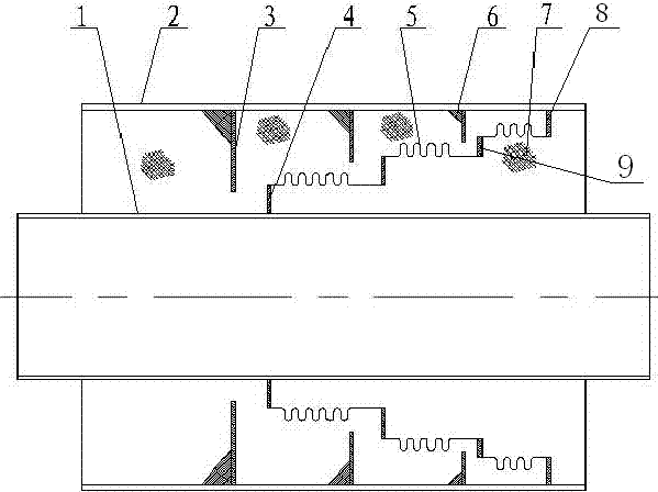
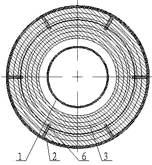
[0010] A large-displacement pipe end sealing device for steam pipelines, which includes: a working tube 1, an outer protective tube 2, and a closing assembly, the sealing assembly is arranged between the working tube 1 and the outer protective tube 2; the sealing assembly includes: a plurality of different Diameter connecting ring plate 4, multiple limiting plates 3 of different diameters, multiple reinforcing rib plates 6, multiple corrugated pipes 5 and high temperature heat-resistant insulation material 7; limiting plate 3 is connected to the inner wall of outer protective tube 2 and uses reinforcing ribs The positioning of the plate 6; the first connecting ring plate 4 is connected to the working pipe 1 and the corrugated pipe 5, the second connecting ring plate 8 is connected to the corrugated pipe 5 and the outer protection pipe 2, and several third connecting ring plates 9 are connected to the corrugated pipe 5 and another corrugated pipe Tube 5; working tube 1 and o...


PUM


Abstract

The invention relates to a closing device for a steam pipe, and belongs to the field of steam heat-insulation pipes. The closing device for the steam pipe comprises a working pipe, an outer protecting pipe and a closing subassembly, wherein the closing subassembly is arranged between the working pipe and the outer protecting pipe and comprises a plurality of connecting annular plates with different diameters, a plurality of limiting plates with different diameters, a plurality of reinforcing rib plates and a plurality of corrugated pipes; the working pipe is connected with one of the corrugated pipes via the first connecting annular plate; one of the corrugated pipes is connected with the outer protecting pipe via the second connecting annular plate; one of the corrugated pipes is connected with the other corrugated pipe via the third connecting annular plates; and the working pipe and the outer protecting pipe form a closed structure through the corrugated pipes and the connecting annular plates. By the closing device for the steam pipe, a complete closing effect can be achieved, and water of the outside is prevented from entering a heat-insulation layer; the service life of the closing device is improved greatly, and the closing device is prevented from failing; a gap is filled with a high-temperature-resistant heat-insulation material, and heat loss of the closing subassembly can be reduced greatly; and large relative displacement in a closed position of the heat-insulation layer of the pipe is allowed, designed layout of pipelines is flexible, investment is reduced relatively, and the reliability is improved.

Description

technical field [0001] The invention relates to a closing device, in particular to a closing device which is used between a steel-sheathed steel steam pipeline working tube and an outer protection tube and can allow the two to form a large relative displacement, which belongs to the field of steam heat preservation pipelines. Background technique [0002] At present, in order to avoid the reduction or even failure of the insulation layer caused by water inflow between the working pipe and the outer protection pipe of the steam pipeline, the insulation layer must be closed in various wells of the pipeline, other open parts of the pipeline, and the middle of some easy-to-water pipelines. space to keep out moisture. When the directly buried steam pipeline adopts a large compensation compensator to reduce the number of pipe fittings such as compensators and fixed joints installed on the pipeline, the working pipe and the outer protective pipe of the directly buried steam pipelin...

Claims


Application Information

Patent Timeline
Patent Type & Authority Applications(China)
IPC IPC(8): F16L27/12
CPCF16L27/125
Inventor 王庆博李晓明杜金超何智慧
Owner CHINA DALIAN KEHUA HEATING PIPE
Learn More