
Power plant boiler spiral slag removal device and installation method

An installation method and technology for power plant boilers, which are applied in the field of engineering installation, can solve problems such as equipment interface position deviation installation cumulative error, impact on unit safety and long-term stable operation, and low water quenching effect of slag, so as to ensure sealing performance, free expansion, Reasonable and compact process

Active Publication Date: 2017-08-29
POWERCHINA SEPCO1 ELECTRIC POWER CONSTR CO LTD
View PDF6 Cites 0 Cited by
  • Summary
  • Abstract
  • Description
  • Claims
  • Application Information

AI Technical Summary

Problems solved by technology

[0004] As an advanced and continuous boiler slag removal device, the spiral slag removal device uses a water-immersed baffle as a sealing device, and the components are scattered and there are many equipment interfaces. Therefore, according to the traditional bottom-up installation method, it is easy to appear equipment The deviation of the interface position and the cumulative error of installation are concentrated on the upper part. When the unit is running, due to the expansion of the heating surface, it is easy to cause air leakage at the bottom of the furnace, low slag water quenching effect, equipment damage, slag leakage and water leakage, which not only increase energy consumption and increase pollution. discharge, and also reduces the efficiency of slag discharge, which affects the safe and long-term stable operation of the unit

Method used


Image

  • Power plant boiler spiral slag removal device and installation method
  • Power plant boiler spiral slag removal device and installation method
  • Power plant boiler spiral slag removal device and installation method

Examples


Embodiment Construction

[0059] In view of the existing defects, the applicant drew on the installation experience of the slag removal machine, and in view of the installation characteristics of the spiral slag removal device, summarized and formed a set of simple, fast and effective installation methods to solve common quality problems such as air leakage and expansion. And improve the construction efficiency.

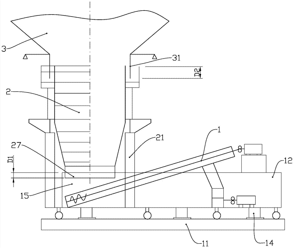
[0060] What is developed is an installation method for the spiral slag removal device, in which the spiral slag removal device includes a spiral slag remover, a slag crusher, a slag well and a slag well self-supporting steel column and other equipment.

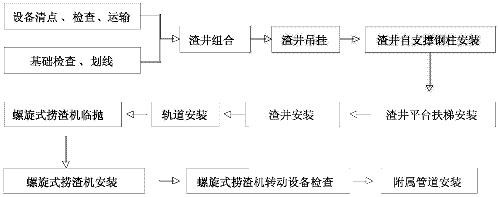
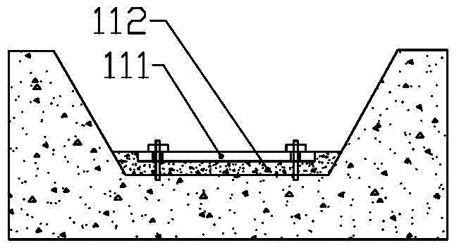
[0061] Such as Figure 1 to Figure 7 As shown, the basic principle is that, according to the structural characteristics of the screw slag remover 1, the screw slag remover track 11 is installed before the installation of the screw slag removal device, and the screw slag remover 1 is pre-placed at the corresponding position. , The slag well 2...


PUM


Abstract

The invention discloses a power station boiler screw deslagging device and a mounting method. The power station boiler screw deslagging device and the mounting method are used for solving the problems of air leakage and mounting difficulty. The device comprises a slag well, a slag well self-supporting steel column, a screw slag conveyor and a slag crusher. The screw slag conveyor is located underthe slag well, and the slag crusher is mounted at the position of a slag outlet of the screw slag conveyor. The device is characterized in that the slag well is mounted between a dry bottom hopper and the screw slag conveyor, the slag well is mounted on a foundation through the slag well self-supporting steel column, an annular water seal is utilized between the dry bottom hopper and the slag well to achieve sealing connection, and a water seal is adopted between the slag well and a water trough of the screw slag conveyor for connection. The invention also discloses an inverted order overlapped mounting method, the influence of errors accumulated to the dry bottom hopper after a heated surface is mounted on the deslagging device is avoided, and the device has the advantages of being good in sealing effect and convenient and fast to mount.

Description

technical field [0001] The invention relates to the technical field of engineering installation such as a spiral slag removal device, in particular to a spiral slag removal device. Background technique [0002] The slag removal device of modern large-scale thermal power plant boiler is an important part of the boiler, which has a great influence on the safety and long-term economic operation of the boiler. The installation quality of the slag removal device affects the air leakage at the bottom of the boiler. Every increase in the air leakage coefficient of 0.1 to 0.2 will reduce the net efficiency of the power plant boiler by 0.2% to 0.5%. For a 300MW unit, it will cause a direct economic loss of 430,000 to 1.1 million yuan per year; at the same time, the air leakage For every 0.1 increase in the coefficient, the power consumption of the induced draft fan will increase by 43kW·h, and the power consumption of the blower will also increase significantly. [0003] At present,...

Claims


Application Information

Patent Timeline
Patent Type & Authority Patents(China)
IPC IPC(8): F23J1/06
Inventor 张崇洋孙巨伟杜传国段继国王建勇曲克刚
Owner POWERCHINA SEPCO1 ELECTRIC POWER CONSTR CO LTD
Learn More