Detecting device for positive and negative surfaces of valve seat ring

A technology for detection devices and valve seat rings, which is applied in the direction of measuring devices, optical devices, instruments, etc., and can solve the problems of high precision requirements and limitations of equipment

Active Publication Date: 2015-08-19
CHONGQING CHANGAN AUTOMOBILE CO LTD
View PDF6 Cites 9 Cited by
  • Summary
  • Abstract
  • Description
  • Claims
  • Application Information

AI Technical Summary

Problems solved by technology

However, due to the small chamfer on the seat ring, the displacement difference caused by the chamfer of the seat ring in this scheme is a small amount, which requires a high

Method used


Image

  • Detecting device for positive and negative surfaces of valve seat ring
  • Detecting device for positive and negative surfaces of valve seat ring
  • Detecting device for positive and negative surfaces of valve seat ring

Examples


Embodiment Construction

[0024] The present invention will be further described below with reference to the drawings and embodiments.

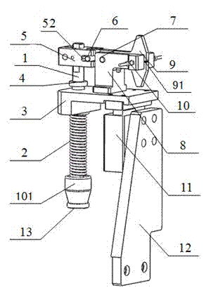
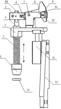
[0025] Such as figure 1 with figure 2 As shown, the main bracket 12 of the detection device is the skeleton of the whole device and bolted to the detection site. The cylinder of the cylinder 11 is fixed to the main bracket 12 by bolts. The piston rod end of the cylinder 11 is bolted to the bottom of the right end of the bracket I3. The left end of I3 is provided with a through hole in the up and down direction. The detection rod 1 penetrates into the through hole and can move up and down along the through hole in a clearance fit. The detection head 101 of the detection rod 1 is facing the seat ring 13 to be detected, and the detection rod 1 is in The part between the bracket I3 and the detection head 101 is sheathed with a spring 2, and the spring 2 is in a compressed state. The bracket I3 presses down the spring 2 to drive the detection head 101 down to contact the seat...


PUM


Abstract

The invention relates to a detecting device for positive and negative surfaces of a valve seat ring. The detecting device comprises a vertical main bracket, wherein the upper part of the main bracket is fixed together with a cylinder barrel of an air cylinder; a piston rod of the air cylinder faces upwards and is fixedly connected with the right end of a bracket I; a detection rod penetrates through a longitudinal seam in the left end part of the bracket I; a detection head is arranged at the lower end of the detection rod; a spring in a compression state sleeves the detection rod between the detection head and the bracket I; a limiting gasket is fixed at the upper part of the detection rod; a clamping block fixed on the detection rod is arranged above the limiting gasket; a limiting slot which penetrates in the front-rear direction is formed in the right end of the clamping block; a bracket II is fixed on the middle part of the bracket I; a pin II in the front-rear direction is arranged at the left end of the bracket II; the pin II is rotationally connected with a light shielding plate; a pin I penetrates through the limiting slot and the left end part of the light shielding plate in the front-rear direction; a photoelectric switch is arranged at the right end of a bracket II; the right end of the light shielding plate is provided with a light through slot corresponding to the photoelectric switch. According to the scheme, the invention provides the detecting device, which adopts a mechanical contact mode and is high in reliability, for positive and negative surfaces of the valve seat ring.

Description

Technical field [0001] The invention relates to an engine cylinder head valve seat ring pressing technology, in particular to a valve seat ring front and back detection device. Background technique [0002] The press-fitting of the engine cylinder head seat ring is a key process in the production process of the engine cylinder head. The quality of the press-fitting and the accuracy of the press-fitting are directly related to the quality and cost of the engine. In order to improve the degree of automation and production efficiency of seat ring assembly and reduce the scrap rate of cylinder heads, at present, fully automatic press-fitting machines automatically convey the seat ring and automatically judge the chamfering direction on the seat ring and follow the correct direction. Pressing into the bottom hole of the seat ring, usually the method of judging the chamfering direction of the seat ring is through the vibrating plate, but the discrimination rate of this method is not hi...

Claims


Application Information

Patent Timeline
IPC IPC(8): G01B11/26
Inventor 钟晋于涛刘彬胡期君林鸿
Owner CHONGQING CHANGAN AUTOMOBILE CO LTD
Why Eureka
Try Eureka