
In-situ observation testing device for simulating micro oil displacing interface

A test device and oil displacement technology, which is applied in measurement devices, instruments, scientific instruments, etc., can solve the problems of late oil displacement technology, failure to observe oil displacement interface, and failure to observe in situ synchronously.

Inactive Publication Date: 2015-08-19
CHINA UNIV OF PETROLEUM (BEIJING)
View PDF4 Cites 23 Cited by
  • Summary
  • Abstract
  • Description
  • Claims
  • Application Information

AI Technical Summary

Problems solved by technology

[0005] The exploitation of crude oil in my country is relatively late, and the application of oil displacement technology is also relatively late. At this stage, the research on oil displacement agents is relatively fast, and there are many applications. However, compared with the macroscopic displacement efficiency of most researches at this stage, the microscopic Mechanism and research are relatively rare in China, and now domestically mainly use crude oil in artificial or natural cores under closed conditions to displace under unobservable conditions; some sand-filling models can be observed, and the main observation is displacement Sweep range and process; oil displacement interface observation was not carried out, let alone in-situ simultaneous observation, so in-situ observation of the mechanism of oil displacement interface in the microscopic oil displacement process and related different flow channels, displacement fluids, crude oil, and temperature The research on the microcosmic oil displacement mechanism under the conditions of pressure and pressure is a very urgent content

Method used


Image

  • In-situ observation testing device for simulating micro oil displacing interface
  • In-situ observation testing device for simulating micro oil displacing interface
  • In-situ observation testing device for simulating micro oil displacing interface

Examples


Embodiment Construction

[0045] The following will clearly and completely describe the technical solutions in the embodiments of the present invention with reference to the accompanying drawings in the embodiments of the present invention. Obviously, the described embodiments are only some of the embodiments of the present invention, not all of them. Based on the embodiments of the present invention, all other embodiments obtained by persons of ordinary skill in the art without making creative efforts belong to the protection scope of the present invention.

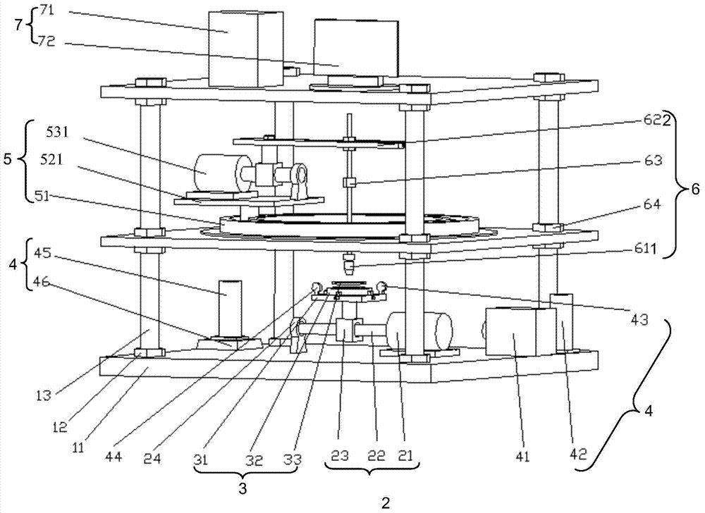
[0046] Such as figure 1 As shown, the embodiment of the present invention provides a simulated microcosmic oil displacement interface in-situ observation test device, and the described simulated microcosmic oil displacement interface in-situ observation test device includes: a base 11, an intermediate seat 111, and a flow channel sample moving assembly 2. Runner sample component 3, oil displacement component 4, microscope movement component 5, mi...


PUM


Abstract

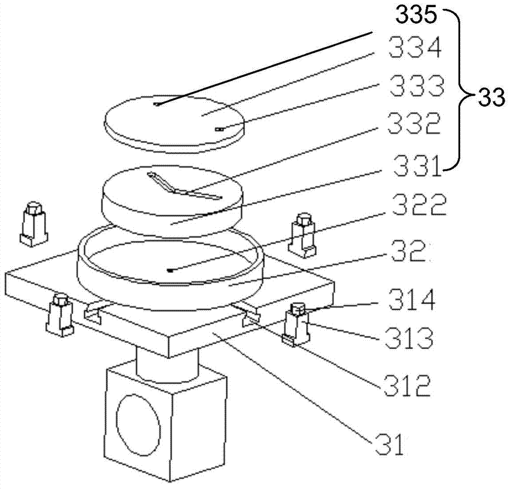
The invention discloses an in-situ observation testing device for simulating a micro oil displacing interface. The in-situ observation testing device comprises a base, a runner test sample movement component, a runner test sample component, an oil displacing component, a microscope movement component, a microscope component and a control acquisition component, wherein the runner test sample movement component comprises a servo motor, a first roller screw rod and a first screw rod screw nut; the runner test sample component comprises a support platform, a temperature control device and a test sample group; the oil displacing component comprises a peristaltic pump, a displacement liquid reagent bottle, inlet pressure acquisition equipment, outlet pressure acquisition equipment, volume measuring equipment and a weighing balance; the microscope component comprises a microscope lens, a microscope support component and an image acquisition device; the control acquisition component is used for acquiring image data and for acquiring and analyzing pressure, volume and mass data, and for controlling the movement of the servo motor and the flow of the peristaltic pump. By adopting the in-situ observation testing device, the interaction of micro surfaces and interfaces among different displacement liquids, crude oil and runners in the crude oil exploration process can be simulated, and study on oil-displacement mechanisms can be promoted.

Description

technical field [0001] The invention relates to the technical field of simulated in-situ observation and test instruments, in particular to an in-situ observation and test device for simulating a microcosmic oil displacement interface. Background technique [0002] With the rapid development of our country's economy, the consumption of petroleum products is increasing, and the import of foreign oil is also increasing. However, the production of some domestic oil fields has bottlenecks, and the cost of extracting crude oil is increasing. The difficulty continues to increase. With the deepening of mining, there are fewer and fewer high-quality oil fields. Therefore, oil flooding, as an important part of the extraction efficiency, is currently attracting everyone's attention. [0003] At this stage, with the gradual deepening of oil extraction, China's oil extraction has gradually entered the later stage, high-quality oil reserves are becoming less and less, oil resources are i...

Claims


Application Information

Patent Timeline
IPC IPC(8): G01N33/00
Inventor 郭岩宝杨柳刘书海王德国周永杰
Owner CHINA UNIV OF PETROLEUM (BEIJING)
Learn More