
Radio telescope broadband electromagnetic shielding effectiveness detection system and detection method thereof

A radio telescope, electromagnetic shielding technology, applied in the measurement of electricity, measurement devices, measurement of electrical variables and other directions, can solve the problems of incomplete detection results, unsatisfactory frequency points, low test efficiency, etc., to avoid influence and high detection efficiency. Effect

Active Publication Date: 2015-08-19
NAT ASTRONOMICAL OBSERVATORIES CHINESE ACAD OF SCI
View PDF8 Cites 11 Cited by
  • Summary
  • Abstract
  • Description
  • Claims
  • Application Information

AI Technical Summary

Problems solved by technology

[0004] 1. The test results are incomplete; since the observation frequency range of the radio telescope is very wide, if a limited frequency point is selected for detection, for example, the frequency points of the conventional test only measure four frequency points of 100MHz, 450MHz, 950MHz, and 3GMHz within the range of 70MHz-3GMHz. The test results are incomplete, and some frequency points cannot meet the requirements, thus interfering with the normal operation of the radio telescope
[0005] 2. Low test efficiency; since there are many shields to be tested, if the test frequency is increased, the workload of manual testing will increase greatly, and the test efficiency will be low
[0006] 3. Radiation affects the health of the testers; because the testers will be exposed to the radiation field due to manual operation, it is not good for the health of the testers
[0007] 4. It is time-consuming and labor-intensive to organize test results; it takes a long time to make test reports manually, and it is easy to cause unobjective test results

Method used


Image

  • Radio telescope broadband electromagnetic shielding effectiveness detection system and detection method thereof
  • Radio telescope broadband electromagnetic shielding effectiveness detection system and detection method thereof
  • Radio telescope broadband electromagnetic shielding effectiveness detection system and detection method thereof

Examples


Embodiment Construction

[0025] The present invention will now be described more fully with reference to the accompanying drawings, in which exemplary embodiments of the invention are shown. This invention may, however, be embodied in many different forms and should not be construed as limited to the exemplary embodiments set forth herein. Rather, these embodiments are provided so that this disclosure will be thorough and complete, and will fully convey the scope of the invention to those skilled in the art.

[0026] For ease of description, spatially relative terms such as "upper," "lower," "left," and "right" may be used herein to describe the relationship of one element or feature relative to another element or feature shown in the figures. It will be understood that the spatial terms are intended to encompass different orientations of the device in use or operation in addition to the orientation depicted in the figures. For example, if the device in the figures is turned over, elements described ...


PUM


Abstract

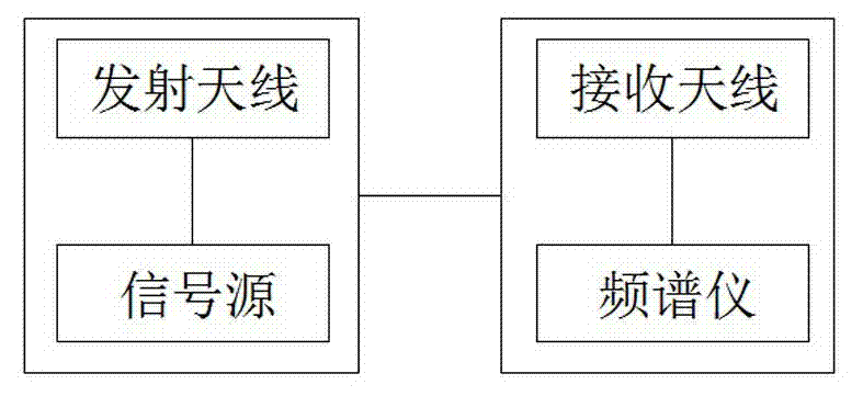
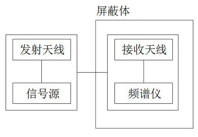
The present invention discloses a radio telescope broadband electromagnetic shielding effectiveness detection system and a detection method thereof. The detection system comprises a transmitting module and a receiving module. The transmitting module comprises a signal source and a transmitting antenna. The signal source is used for emitting an electrical signal with specified frequency and the electrical signal is emitted by the transmitting antenna. The receiving module comprises a spectrum analyzer and a receiving antenna which is used for receiving the electrical signal emitted by the signal source and transmitting the received electrical signal to the spectrum analyzer. The spectrum analyzer is electrically coupled to the signal source to ensure the synchronization of sending and receiving the electrical signal. The spectrum analyzer receives electrical signals emitted before and after the signal source is placed into a shielding body, and thus the shielding performance of the shielding body is calculated. The detection system can detect a plurality of frequency points in a frequency band, the detection efficiency is high, the influence of a manual test on a tester is avoided, a detection result report is generated automatically, and time and labor are saved.

Description

technical field [0001] The invention relates to the field of electromagnetic shielding effectiveness detection, in particular to a radio telescope broadband electromagnetic shielding effectiveness detection system and detection method. Background technique [0002] Radio astronomy telescopes observe very weak radio signals from the universe, and the receiving frequency band can cover the frequency range from tens of MHz to hundreds of GHz. Due to the extremely high sensitivity of the radio telescope, it is very easy to receive radio interference from the outside world and itself, thus affecting normal operation and scientific output. Take the 500-meter Aperture Spherical Radio Telescope (FAST), a national major scientific and technological infrastructure, as an example. Its operating frequency is 70MHz-3000MHz. After completion, it will become the largest radio telescope in the world. Also very high, radio interference from the ground can affect the work of radio astronomy ...

Claims


Application Information

Patent Timeline
IPC IPC(8): G01R31/00
Inventor 岳友岭甘恒谦胡浩张海燕孙京海吴明长南仁东
Owner NAT ASTRONOMICAL OBSERVATORIES CHINESE ACAD OF SCI
Learn More