laser range finder

A laser rangefinder and optical path technology, applied in the field of laser rangefinders, can solve the problems of increased measurement error, poor workmanship, and the inability to increase the optical fiber receiving surface indefinitely, so as to reduce the distance measurement error and increase the received light intensity. Effect

Active Publication Date: 2017-02-15
CHANGZHOU XINRUIDE INSTR
View PDF7 Cites 2 Cited by
  • Summary
  • Abstract
  • Description
  • Claims
  • Application Information

AI Technical Summary

Problems solved by technology

[0006] 3. The end face of the optical fiber is fixed on the focal point of the optical system. When measuring at close distances, the focal position moves backward due to the imaging of the optical system, and the light-receiving surface of the optical fiber needs to be increased. Otherwise, the energy received into the receiving optical fiber will decrease, resulting in measurement The error increases; the light-receiving surface of the optical fiber cannot be increased infinitely, and the larger the light-receiving surface, the greater the external light noise, and the measurement error will increase; at the same time, the thicker the optical fiber is, the harder it is, and the worse the manufacturing process is.

Method used


Image

  • laser range finder
  • laser range finder
  • laser range finder

Examples


Embodiment 1

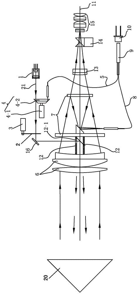
[0027] see figure 2 , The laser rangefinder of this embodiment includes: a transmitting optical system, a receiving optical system, and a ranging control and calculation circuit system.

[0028] The transmitting optical system includes an aperture 2, a laser, and a collimator 1 arranged at the light output end of the laser.

[0029] The diaphragm 2 is a rectangular aperture diaphragm. One end of the aperture 2 is fixedly connected with the rotating shaft of the conversion motor 3, and the conversion motor 3 is used to control the aperture 2 to move into or out of the emission optical path 21 of the emission optical system.

[0030] On the transmitting optical path 21 at the front end of the collimator 1, a first refraction plate 22 for generating an inner optical path 24 for sampling is provided, and an inner optical fiber 5 for receiving light from the inner optical path 24; An internal optical path switching device 4 is provided between the optical paths 24.

[0031] The internal ...

Embodiment 2

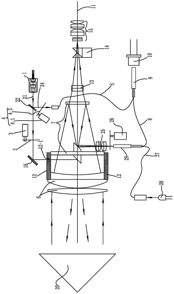
[0049] On the basis of embodiment 1, the modification of this embodiment is that: one side of the first refraction plate 22 is provided with a second refraction plate arranged in parallel with the first refraction plate 22 for extending the inner optical path 24 23. The light blocking sheet 4-3 is arranged on the inner light path 24 and downstream of the second refraction plate 23, and downstream of the first refraction plate 22 on the emission light path 21.

[0050] The rest of the structure is consistent with embodiment 1.


PUM


Abstract

The invention relates to a laser range finder. The laser range finder comprises an emission optical system. The emission optical system comprises a collimator. An emission light path on which the collimator is arranged is provided with a first refraction plate used for generating an inner light path so as to realize sampling, and an inner light path optical fiber used for receiving the inner light path. An inner and outer light path switching device is arranged between the emission light path and the inner light path. The inner and outer light path switching device blocks the emission light path and conducts the inner light path, so that the purpose of inner light path measuring is achieved; when the inner light path is blocked, the emission light path is conducted, so that the purpose of outer light path measuring is realized. By adopting the structure, the negative influences of axial endplay of an inner light path motor shaft to measuring precision in the prior art are avoided.

Description

Technical field [0001] The invention relates to a laser rangefinder. Background technique [0002] The basic mechanism of a laser distance measuring device is well known. For example: Chinese Patent Document Announcement No. CN201203670Y discloses that the transmitting optical system in a laser rangefinder includes: a diaphragm 2, a laser, and a collimator 1 arranged at the light output end of the laser; and the diaphragm shift device is used to control the light The stop 2 moves in or out of the emission optical path 21 of the emission optical system. An inner optical path switching device 4 for refracting light is provided on the transmitting optical path 21 at the front end of the collimator 1, and an inner optical path fiber 5 for receiving the refracted light is provided on one side of the inner optical path switching device 4; The light path switching device 4 includes: an inner light path motor 4-1 and a refraction prism 4-2 fixedly connected to the rotating shaft of the...

Claims


Application Information

Patent Timeline
Patent Type & Authority Patents(China)
IPC IPC(8): G01S17/08G01S7/481
CPCG01S7/4814G01S17/08
Inventor 巢海步
Owner CHANGZHOU XINRUIDE INSTR
Why Eureka
Try Eureka