
Gap Iron Core Rogowski Coil Transformer Based on Magnetometer Compensation

A Rogowski coil and magnetic potentiometer technology, applied in the direction of inductors, transformers/inductor coils/windings/connections, transformers, etc., can solve design and material selection limitations, excitation characteristics current sensing errors, impossible to completely eliminate errors, etc. The problem is to reduce the number of turns of the secondary coil, eliminate nonlinear errors, and shorten the length of the equivalent air gap.

Active Publication Date: 2017-05-03
CHINA JILIANG UNIV
View PDF6 Cites 0 Cited by
  • Summary
  • Abstract
  • Description
  • Claims
  • Application Information

AI Technical Summary

Problems solved by technology

However, since the magnetic circuit of the gapped iron core Rogowski coil is composed of the air gap magnetic circuit and the iron core magnetic circuit in series, the excitation characteristics of the iron core will bring nonlinearity to the current sensing of the gapped iron core Rogowski coil error
This error can be reduced by using high-permeability iron core materials and a suitable ratio of the air gap magnetic circuit length to the iron core magnetic circuit length, but this limits the design and material selection of the gapped iron core Rogowski coil. At the same time, it is impossible to completely eliminate this error
Therefore, it is considered to use a magnetometer to detect the excitation state of the iron core, and to perform online compensation for the sensing error caused by the iron core, so that the gapped iron core Rogowski coil is equivalently an ideal effective air gap magnetic circuit Air-core Rogowski coils with very short length, and digital and analog integral circuits are used to restore the integral of the output signal. At present, there are no patents and Other literature reports

Method used


Image

  • Gap Iron Core Rogowski Coil Transformer Based on Magnetometer Compensation
  • Gap Iron Core Rogowski Coil Transformer Based on Magnetometer Compensation
  • Gap Iron Core Rogowski Coil Transformer Based on Magnetometer Compensation

Examples


Embodiment Construction

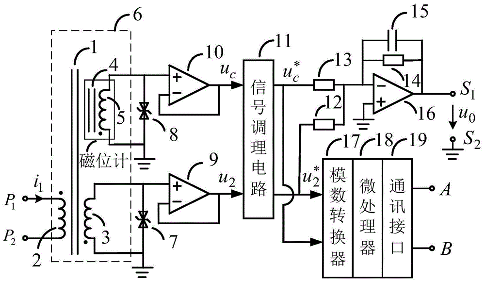
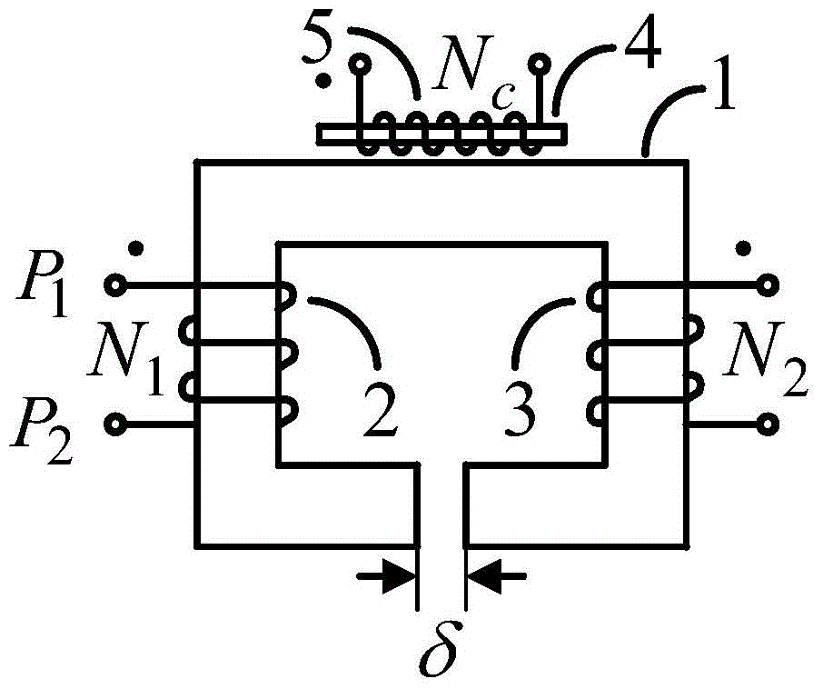
[0034] The band-gap iron core type Rogowski coil transformer based on magnetometer compensation proposed by the present invention, its embodiment is as follows figure 1 and figure 2 As shown, it includes a closed-loop iron core 1 with a gap, a primary coil 2, a secondary coil 3, a magnetometer skeleton 4, a magnetometer coil 5, an annular shielding box with slotted inner ring 6, a first two-way voltage regulator tube 7. The second bidirectional voltage regulator tube 8, the first operational amplifier 9, the second operational amplifier 10, the signal conditioning circuit 11, the first resistor 12, the second resistor 13, the third resistor 14, the integrating capacitor 15, and the third operational amplifier 16. Analog-to-digital converter 17, microprocessor 18 and communication interface 19; the magnetometer skeleton 4 and the magnetometer coil 5 constitute the magnetometer, and the closed-loop iron core 1 with gaps, the primary coil 2 and the secondary coil 3 constitute T...


PUM

PropertyMeasurementUnit
radiusaaaaaaaaaa
thicknessaaaaaaaaaa
lengthaaaaaaaaaa

Abstract

The invention discloses a gapped core-type Rogowski coil transformer based on magnetic potentiometer compensation. The gapped core-type Rogowski coil transformer comprises a gapped closed-loop core, a primary coil, a secondary coil, a magnetic potentiometer framework, a magnetic potentiometer coil, an inner-loop-grooved annular shielding box, a first bilateral voltage-regulator tube, a second bilateral voltage-regulator tube, a first operational amplifier, a second operational amplifier, a signal conditioning circuit, a first resistor, a second resistor, a third resistor, an integrating capacitor, a third operational amplifier, an analog-digital converter, a microprocessor and a communication interface. According to the transformer, the sensing error of a gapped core-type Rogowski coil is compensated with a magnetic potentiometer, so that a voltage analog quantity and a digital quantity which are in linear proportional relations with primary current containing harmonic waves can be output. Through adoption of the gapped core-type Rogowski coil transformer, the problems of small output signal and low accuracy in a hollow Rogowski coil are solved; the problem of non-linear errors generated by a core in the gapped core-type Rogowski coil transformer is solved; and accurate sensing of primary current fundamental waves and harmonic components is realized.

Description

technical field [0001] The invention belongs to the technical field of electromagnetic measurement, and in particular relates to an electronic current transformer capable of accurately measuring current fundamental waves and harmonics at the same time, in particular to a gapped iron core Rogowski coil transformer based on magnetometer compensation . Background technique [0002] Electronic current transformer is a kind of current sensor, which is mainly used for the measurement of grid current. The national standard GB / T20840.8-2007 "Transformer Part 8: Electronic Current Transformer" provides technical specifications for the fundamental and harmonic accuracy of electronic current transformers, and the national standard GB / T14549-1993 "Power Quality Public Power Grid Harmonics" gives the limit value of public power grid harmonic current. The national standard GB / T19862-2005 "General Requirements for Power Quality Monitoring Equipment" stipulates the general requirements for...

Claims


Application Information

Patent Timeline
Patent Type & Authority Patents(China)
IPC IPC(8): H01F38/32H01F27/28G01R19/25
Inventor 谢岳
Owner CHINA JILIANG UNIV
Learn More