
Lumped element antenna

A lumped element and antenna technology, applied in antennas, electrical components, etc., can solve problems such as strong temperature sensitivity and applicability limitations, and achieve the effects of small size, good stability, and strong temperature insensitivity

Inactive Publication Date: 2015-08-19
王少夫
View PDF3 Cites 0 Cited by
  • Summary
  • Abstract
  • Description
  • Claims
  • Application Information

AI Technical Summary

Problems solved by technology

[0003] However, due to the problem of its circuit structure, the traditional antenna is extremely sensitive to temperature, and its applicability is greatly limited.

Method used


Image

  • Lumped element antenna
  • Lumped element antenna

Examples


Embodiment Construction

[0009] The present invention will be described in further detail below in conjunction with the accompanying drawings.

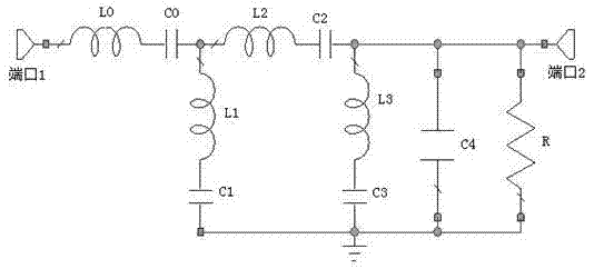
[0010] combine figure 1 , the present invention is a lumped element antenna, which is described in detail by selecting an example of a passenger band, including two port 1 (Port1) and port 2 (Port2); four series LC resonant units, a grounding capacitor and a resistor implementation; where port 1 is connected to One end of the resonant unit is connected, The other end of the resonance unit and the resonance unit One end of the connection; the resonant unit The other end is connected to the ground; the resonant unit one end with One end of the connection is connected, and each port is connected to an impedance of 1 ohm. Each device is implemented using lumped elements. Its circuit structure can realize signal sending and receiving in the 10KHz-80GHz frequency band.

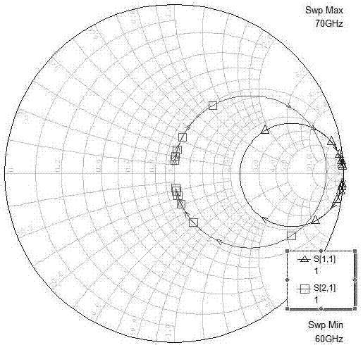
[0011] combine figure 2 , it can be seen from the simulation results that the S...


PUM


Abstract

The invention discloses a lumped element antenna, and a circuit structure consists of four serial LC resonance units, one grounding capacitor, and one resistor. The antenna can be widely used in a wireless mobile communication system. The antenna is simple in structure, is small in size, is convenient to use, is excellent in performance, and facilitates the integration of a circuit.

Description

technical field [0001] The invention belongs to antennas, in particular to a lumped element antenna. It belongs to the field of electronics and communication. Background technique [0002] In recent years, a series of researches on antennas have been carried out at home and abroad. In a specific frequency band, many achievements have been made, especially in WCDMA technology. Antennas play an important role in systems such as microwave communication, electronic countermeasures, microwave measurement, and phased radar components. For example, in the base station and mobile system of mobile communication, the antenna is used as a common device connecting the receiving and transmitting circuits with the antenna; the purpose of improving system stability and reliability. [0003] However, due to the problem of its circuit structure, the traditional antenna is extremely sensitive to temperature, and its applicability is greatly limited. The present invention can effectively s...

Claims


Application Information

Patent Timeline
IPC IPC(8): H01Q23/00
Inventor 不公告发明人
Owner 王少夫
Features
  • Generate Ideas
  • Intellectual Property
  • Life Sciences
  • Materials
  • Tech Scout
  • Unparalleled Data Quality
  • Higher Quality Content
  • 60% Fewer Hallucinations
Learn More