Electronic equipment and circuit board connection method
A technology of electronic equipment and circuit boards, which is applied in the electronic field and can solve the problems of increasing the size of circuit boards and unfavorable development of miniaturization of electronic equipment.
- Summary
- Abstract
- Description
- Claims
- Application Information
AI Technical Summary
Problems solved by technology
Method used
Image
Examples
Embodiment 1
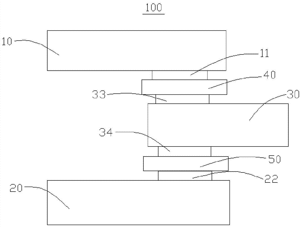
[0038] Such as figure 1 As shown, it is a schematic structural diagram of an electronic device 100 in a preferred embodiment of the present application. The electronic device 100 may be any device including a circuit board, such as a computer, a mobile phone, a television, a refrigerator, an air conditioner, a server, and the like. The electronic device 100 includes a first circuit board 10 , a second circuit board 20 , a third circuit board 30 , a first anisotropic conductive adhesive film 40 and a second anisotropic conductive adhesive film 50 .
[0039] The first circuit board 10 includes first pins 11 .
[0040] The second circuit board 20 includes a second pin 22 .
[0041] The third circuit board 30 is arranged between the first circuit board 10 and the second circuit board 20, and the third circuit board 30 is provided with a third pin 33 and the third pin 33 The position corresponds to and opposite to the fourth pin 34 .
[0042] Specifically, the first pin 11, the...
Embodiment 2
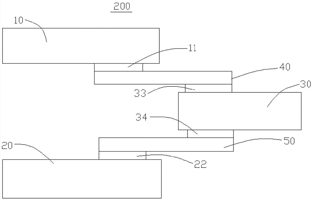
[0062] Such as figure 2 As shown, it is a schematic structural diagram of an electronic device 200 in another preferred embodiment of the present application; the difference between the electronic device 200 and the electronic device 100 is only that: the first anisotropic conductive adhesive film 40 and the second anisotropic conductive adhesive The lengths of the films 50 are different, the relative positions of the first circuit board 10 and the third circuit board 30 are different, and the relative positions of the second circuit board 20 and the third circuit board 30 are different.
[0063] Specifically, in this embodiment, the lengths of the first anisotropic conductive adhesive film 40 and the second anisotropic conductive adhesive film 50 are longer than the lengths of the first anisotropic conductive adhesive film 40 and the second anisotropic conductive adhesive film 50 in Example 1. The length of the second anisotropic conductive adhesive film 50, due to the incre...
Embodiment 3
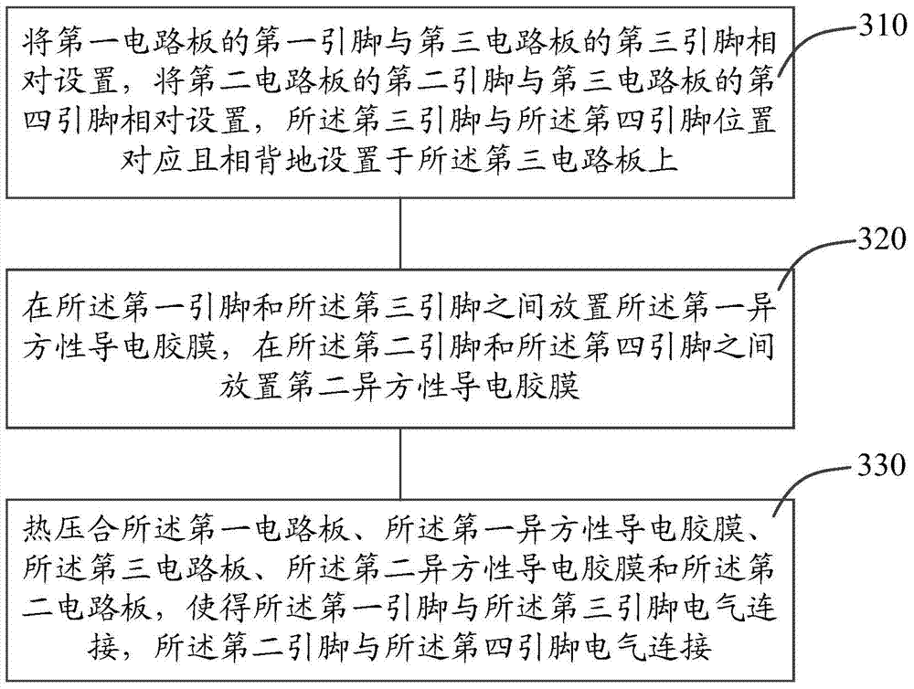
[0065] Such as image 3 As shown, it is a flow chart of another preferred embodiment of the circuit board connection method of the present application. The circuit board connection method includes the following steps:
[0066] Step 310, arrange the first pin of the first circuit board opposite to the third pin of the third circuit board, and arrange the second pin of the second circuit board opposite to the fourth pin of the third circuit board, so The third pin corresponds to the position of the fourth pin and is arranged oppositely on the third circuit board;
[0067] Step 320, placing the first anisotropic conductive adhesive film between the first pin and the third pin, and placing a second anisotropic conductive film between the second pin and the fourth pin Anisotropic conductive film;
[0068] Step 330, hot pressing the first circuit board, the first anisotropic conductive adhesive film, the third circuit board, the second anisotropic conductive adhesive film and the...
PUM
 Abstract
Description
Claims
Application Information
 - R&D
- Intellectual Property
- Life Sciences
- Materials
- Tech Scout
- Unparalleled Data Quality
- Higher Quality Content
- 60% Fewer Hallucinations
Browse by: Latest US Patents, China's latest patents, Technical Efficacy Thesaurus, Application Domain, Technology Topic, Popular Technical Reports.
© 2025 PatSnap. All rights reserved.Legal|Privacy policy|Modern Slavery Act Transparency Statement|Sitemap|About US| Contact US: help@patsnap.com


