Compensating circuit for restraining torque ripple of brushless DC motor

A technology of brush DC motor and torque ripple, applied in the direction of torque ripple control, etc., can solve the problems of non-commutation current fluctuation, commutation torque ripple, etc., and achieve the effects of low cost, easy engineering implementation, and simple control mode

Active Publication Date: 2015-08-19
HARBIN ENG UNIV
View PDF4 Cites 8 Cited by
  • Summary
  • Abstract
  • Description
  • Claims
  • Application Information

AI Technical Summary

Problems solved by technology

During commutation, the current of the off-phase is reduced by the freewheeling diode, and the current of the on-phase is increased by the voltage source. Since the rate of decline of the off-phase current is inconsistent with the rate of rise of the on-phase current, the non-commutation current fluctuates, causing commutation torque ripple

Method used


Image

  • Compensating circuit for restraining torque ripple of brushless DC motor
  • Compensating circuit for restraining torque ripple of brushless DC motor
  • Compensating circuit for restraining torque ripple of brushless DC motor

Examples


Embodiment

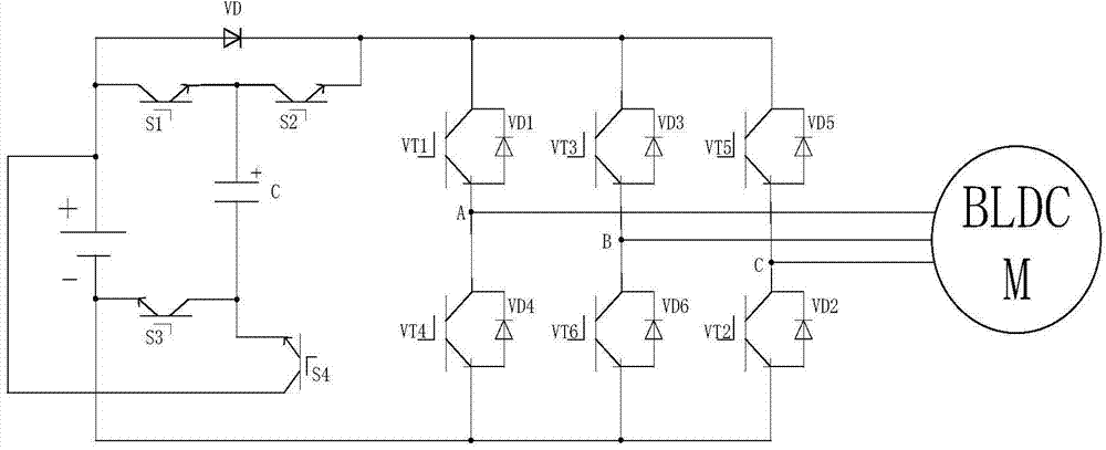
[0034] The invention adopts a brushless DC motor with a rated power of 3.7kW, a rated voltage of 300V, and a rated speed of 1500rmp. The measured inductance is 0.188425mH, and the amplitude of the counter electromotive force is 92.99V. Therefore, the compensation voltage, that is, the voltage across the capacitor is 71.96V.

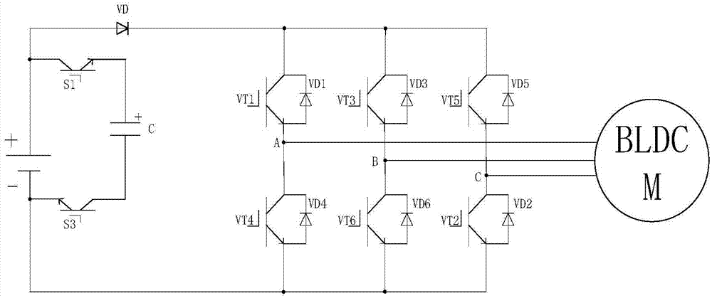
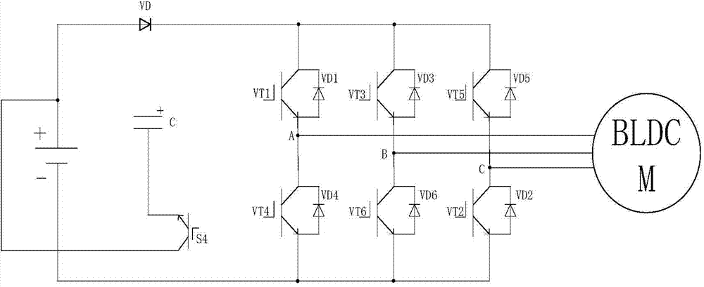
[0035] image 3 In (a), the driving voltage is a DC voltage of 300V during non-commutation, and the driving voltage is a DC voltage plus a compensation voltage of 371.96V during commutation. Figure 4 with Image 6 It is the three-phase current waveform diagram and the current torque waveform diagram of the embodiment under the control of the method of the present invention. When the motor commutates, it can be seen that the rate of decline of the off-phase current is inconsistent with the rate of rise of the conduction phase current, and the non-commutation current There are fluctuations, which cause commutation torque ripple, the average torque is 26N*...


PUM


Abstract

The invention belongs to the field of brushless DC motor control, and particularly relates to a compensating circuit for restraining torque ripple of a brushless DC motor. The compensating circuit comprises a DC voltage source U, a diode VD, a capacitor C, a switching transistor S1, a switching transistor S2, a switching transistor S4, a three-phase inverter bridge and a brushless DC motor, and is characterized in that a charging circuit is formed in a mode that a positive electrode of the DC voltage source U is connected to a collector electrode of the switching transistor S1, a negative electrode of the DC voltage source is connected to an emitting electrode of the switching transistor S3, a positive electrode of the capacitor is connected to an emitting electrode of the switching transistor S1, and a negative electrode of the capacitor is connected to a collector electrode of the switching transistor S3; and a voltage compensating circuit is formed by connecting a collector electrode of the switching transistor S4 to the positive electrode of the DC voltage source U. The voltage compensating circuit formed by four electric power switching transistors, one electric power diode and one capacitor can effectively restrain the commutation torque ripple, and is simple in control mode, low in cost and easy for engineering implementation.

Description

technical field [0001] The invention belongs to the control field of brushless direct current motors, in particular to a compensation circuit for suppressing torque ripple of brushless direct current motors. Background technique [0002] Brushless DC motors have the advantages of simple structure and large torque, and are widely used in various industries. They are considered to be the electronically controlled motors with the most development prospects and wide application prospects in the 21st century. However, there is torque ripple in the motor, which hinders its development to the field of high power and high precision. [0003] The brushless DC motor consists of three parts: the motor body, the position sensor and the commutation switch. The position sensor detects the rotor position of the motor, converts the position signal into an electrical signal, controls the commutation switch to be turned on and off, and the DC voltage source drives the motor to rotate stably....

Claims


Application Information

Patent Timeline
Patent Type & Authority Applications(China)
IPC IPC(8): H02P6/10
CPCH02P6/10
Inventor 姚绪梁江晓明杨光仪张燕冯丽媛常英健王峰孟令卫王晓伟徐海洋
Owner HARBIN ENG UNIV
Why Eureka
Try Eureka