
A Commutation Torque Ripple Suppression Method for Brushless DC Motor

A brushed DC motor and fluctuation suppression technology, applied in the direction of torque ripple control, etc., can solve the problems of large voltage stress of switching devices, large voltage stress, many switching elements and passive devices, etc., so as to improve the utilization rate and reduce the cost. Effect

Active Publication Date: 2021-10-22
TIANJIN UNIV
View PDF9 Cites 0 Cited by
  • Summary
  • Abstract
  • Description
  • Claims
  • Application Information

AI Technical Summary

Problems solved by technology

However, since the Z-source network can only provide a boost mechanism, the switching devices of the inverter bridge are subjected to large voltage stress
[0005] There are still some problems in the existing method of adjusting the DC side voltage by introducing a boost converter to suppress the commutation torque fluctuation in the full speed range: the switching elements and the wireless power required by the method based on the two-stage DC-DC boost inverter There are relatively many source devices, and the utilization rate of the DC power supply voltage is low; the control method based on the Z-source inverter has a large voltage stress on the switching devices on the inverter bridge during the commutation phase and the normal conduction phase

Method used


Image

  • A Commutation Torque Ripple Suppression Method for Brushless DC Motor
  • A Commutation Torque Ripple Suppression Method for Brushless DC Motor
  • A Commutation Torque Ripple Suppression Method for Brushless DC Motor

Examples


specific example

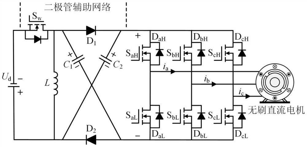
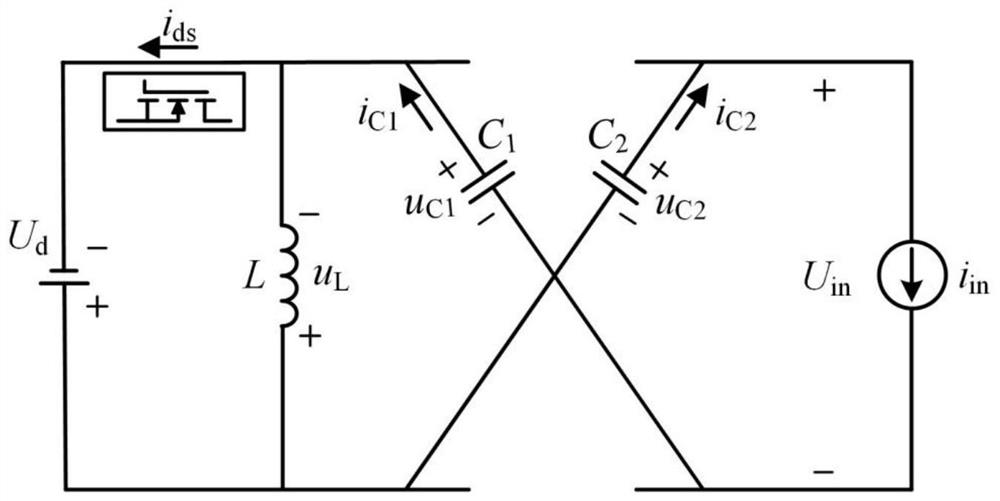
[0074] according to figure 2 The front-end MOS tube S shown w The switching state of the diode-assisted buck-boost inverter has two working modes. exist Figure 3a , when S w conduction, that is, S w =ON, the inductor voltage u L , DC side voltage U in can be expressed as

[0075]

[0076] In formula (1), U d is the supply voltage, U on for S w DC link voltage at turn-on, U C is the capacitance C 1 and C 2 average voltage.

[0077] exist Figure 3b , when S w shutdown, that is, S w =OFF, the inductor voltage u L , DC side voltage U in for

[0078]

[0079] In formula (2), U off for S w DC link voltage at shutdown.

[0080] Combined with the volt-second balance equation of the inductance L, U can be obtained C for

[0081]

[0082] In formula (3), k on For MOS tube S w conduction duty cycle.

[0083] Therefore, in one modulation period, according to the MOS tube S w The switching state, the DC side voltage has two different constant values ​...


PUM


Abstract

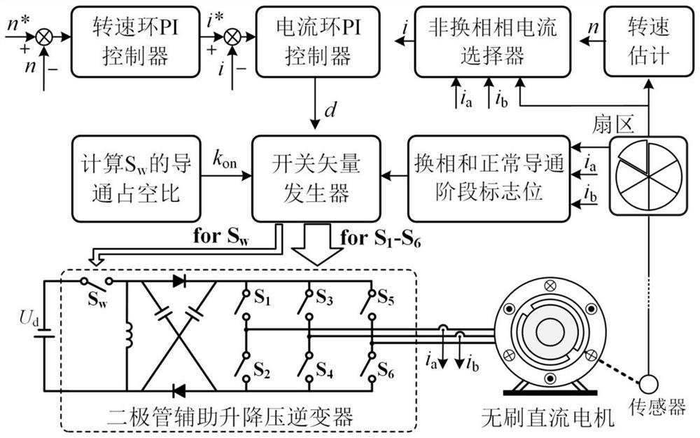
A method for suppressing commutation torque fluctuations of brushless DC motors: a diode auxiliary network is set between the DC power supply and the three-phase inverter bridge, and a brushless DC motor system driven by a diode-assisted buck-boost inverter is constructed ; According to the switching mode of the power device in the diode-assisted buck-boost inverter and the two-phase conduction mode of the brushless DC motor, four kinds of switching vectors of the diode-assisted buck-boost inverter are designed; in the commutation stage, according to different switch The effect of vector interaction on commutation torque fluctuation suppression, arrange the action sequence of each vector in each modulation cycle, and derive the duty cycle of the corresponding switch vector action; in the normal conduction stage, by analyzing the action of different switch vectors For the influence of brushless DC motor speed regulation, the action sequence of different switch vectors and the duty cycle of the corresponding switch vector actions are designed. The invention can be applied to the fields of motor speed regulation, power electronic control and the like, and can make the motor run smoothly.

Description

technical field [0001] The invention relates to a method for suppressing commutation torque ripple. In particular, it relates to a commutation torque ripple suppression method for a brushless DC motor. Background technique [0002] Brushless DC motors have the advantages of small size, simple structure, and high power density, and are increasingly widely used in industrial control, aerospace and other fields. However, the motor suffers from torque fluctuations during commutation because the motor inductance and limited DC-link voltage hinder the rapid change of phase current during commutation. Large commutation torque fluctuations will cause vibration and noise of the motor system and reduce the load capacity of the motor, which is one of the main problems that limit the high-performance operation of brushless DC motors. [0003] In recent years, scholars have conducted in-depth research on commutation torque ripple suppression. Based on the traditional voltage source in...

Claims


Application Information

Patent Timeline
Patent Type & Authority Patents(China)
IPC IPC(8): H02P6/10
CPCH02P6/10
Inventor 史婷娜曹彦飞李新旻陈炜夏长亮
Owner TIANJIN UNIV
Learn More