
Photovoltaic assembly

A technology for photovoltaic modules and unit groups, applied in the field of solar power generation, can solve the problems of cumbersome manufacturing, long bus bars, complicated bus bar wiring, etc., to achieve the effects of simple wiring, reduced energy loss, and improved output power

Inactive Publication Date: 2015-08-19
CSI SOLAR POWER GROUP CO LTD +1
View PDF8 Cites 6 Cited by
  • Summary
  • Abstract
  • Description
  • Claims
  • Application Information

AI Technical Summary

Problems solved by technology

However, in the prior art, no matter whether the photovoltaic module has a full-piece or a half-piece battery, it is a single junction box. In order to prevent hot spots, each battery string needs to be connected to the corresponding lead-out bus bar to connect to the diodes in the junction box, as attached figure 1 In the structure display of the photovoltaic module 100', since the diodes are collectively arranged in the same junction box 11, after the battery strings 12 are connected in parallel by the bus bars, it is still necessary to connect the positive and negative poles of the battery strings 12 to the The two ends of the corresponding diodes in the junction box 11, in this way, make the bus bars extend longer, and insulation strips need to be used between the multiple bus bars and the battery sheets for insulation, so that the bus bars in the entire photovoltaic module 100' The wiring method is more complicated, and the manufacturing is more cumbersome

Method used


Image

  • Photovoltaic assembly
  • Photovoltaic assembly
  • Photovoltaic assembly

Examples


Embodiment Construction

[0022] The present invention will be described in detail below with reference to the embodiments shown in the accompanying drawings. However, this embodiment does not limit the present invention, and any structural, method, or functional changes made by those skilled in the art according to this embodiment are included in the protection scope of the present invention.

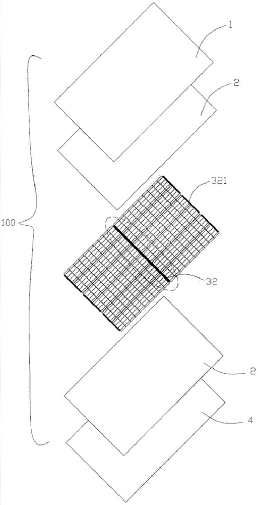
[0023] Please refer to Figure 2 to Figure 5 Shown is a preferred embodiment of the photovoltaic module 100 of the present invention. The photovoltaic module 100 includes a battery module formed by laminating a glass cover 1 , an encapsulant film 2 , a combination of battery strings and a backplane 4 , and several junction boxes 5 . The junction box 5 is installed on the backplane 4 and connected with the battery string combination.

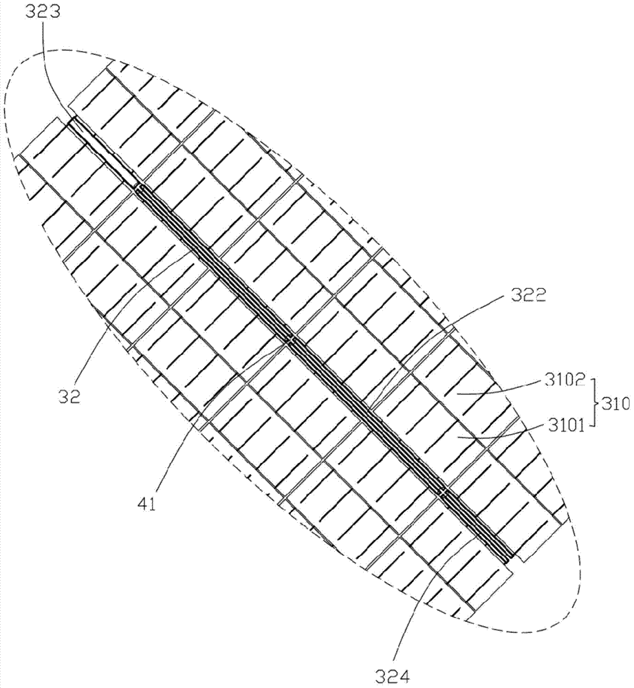
[0024] Please refer to Figure 2 to Figure 4 As shown, the battery string combination includes a plurality of battery strings 31 parallel to each other and extending longitudin...


PUM


Abstract

The invention provides a photovoltaic assembly, which comprises a plurality of battery strings and a backboard, wherein the plurality of battery strings are parallel to each other and extend along the longitudinal direction, and the backboard is used for bearing the battery strings. The plurality of battery strings are symmetrically distributed on a light receiving surface of the backboard in a two-column mode along the longitudinal direction and form a plurality of unit groups which are sequentially connected in series. Each battery string is provided with an outer end which is close to the edge of the backboard along the longitudinal direction and an inner end which is close to a middle position of the backboard. Each unit group comprises two battery strings which are connected in series at the outer end by adopting a first bus bar and adjacently arranged side by side. The photovoltaic assembly further comprises a plurality of junction boxes arranged on a backlight surface of the backboard, wherein the junction boxes are arranged at intervals along the transverse direction and located at the middle position of the backboard along the longitudinal direction, the two battery strings in each unit group are enabled to share the same junction box, each junction box is internally provided with diodes, and the inner ends of the two battery strings in each unit group are connected to a positive electrode and a negative electrode of the diode in the corresponding junction box. Therefore, a problem of complex wiring of bus bars can be effectively solved.

Description

technical field [0001] The invention relates to the technical field of solar power generation, in particular to a photovoltaic module with simple structure and convenient manufacture. Background technique [0002] Photovoltaic modules, as the core components of solar photovoltaic power generation systems, are composed of laminated battery modules, junction boxes and other external functional modules. The external functional module may be a device for realizing current conversion, such as an inverter. Wherein, the battery assembly is formed by lamination of glass, encapsulation film, battery series combination and back plate. The battery string combination includes several battery strings connected together by bus bars. The most widely used battery series at the present stage is usually formed by connecting several whole battery pieces in series. [0003] However, due to the high loss of the full-piece battery, some battery components composed of half-piece batteries are g...

Claims


Application Information

Patent Timeline
IPC IPC(8): H02S40/34H02S40/36
CPCH01L31/0504Y02E10/50
Inventor 林洪良刘德志沈坚
Owner CSI SOLAR POWER GROUP CO LTD
Features
  • Generate Ideas
  • Intellectual Property
  • Life Sciences
  • Materials
  • Tech Scout
  • Unparalleled Data Quality
  • Higher Quality Content
  • 60% Fewer Hallucinations
Learn More