inorganic barrier layer
A technology of barrier layer and exciton barrier layer, applied in organic semiconductor devices, radiation therapy, treatment, etc., can solve the problem of unsatisfactory device efficiency
- Summary
- Abstract
- Description
- Claims
- Application Information
AI Technical Summary
Problems solved by technology
Method used
Image
Examples
Embodiment 1
[0134] Material
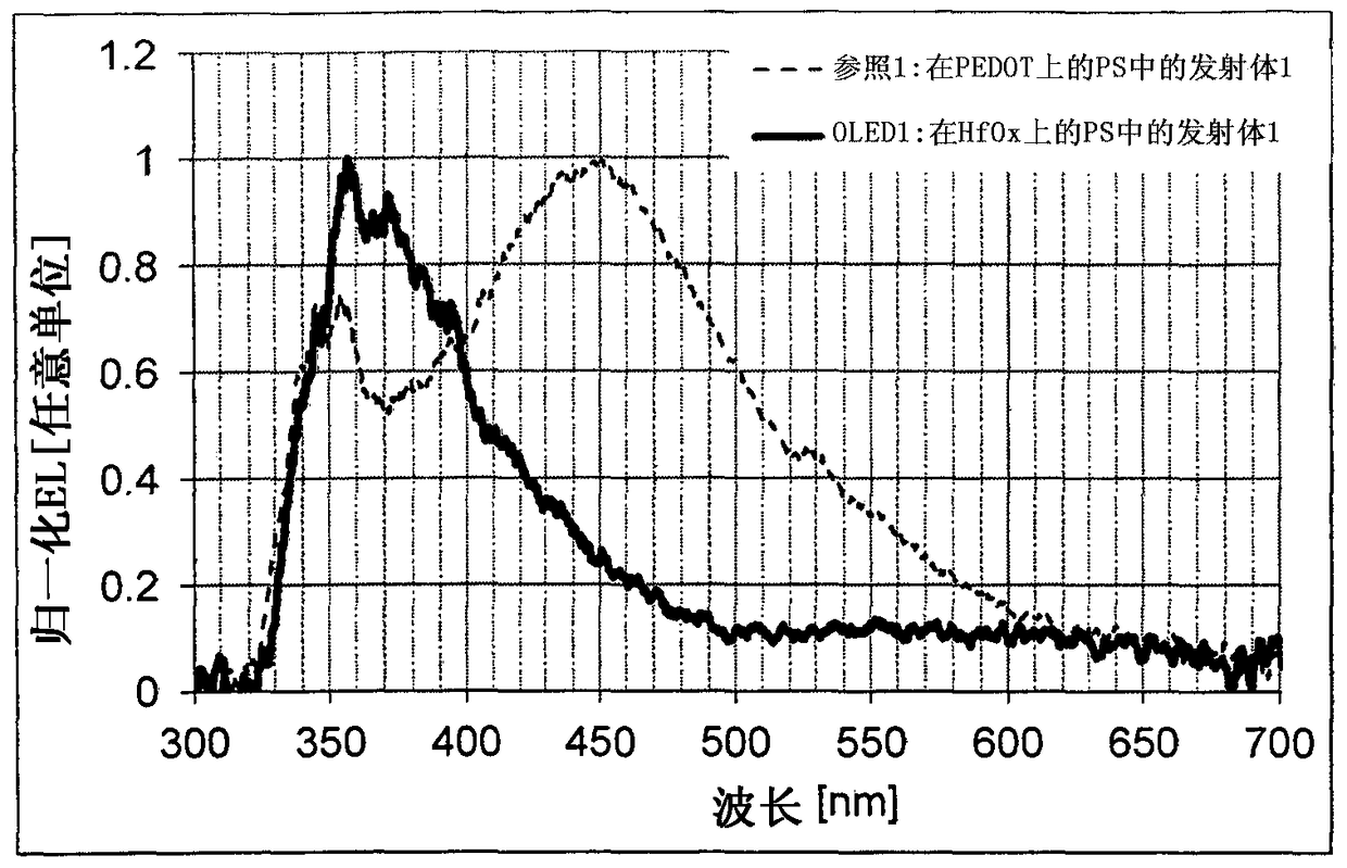
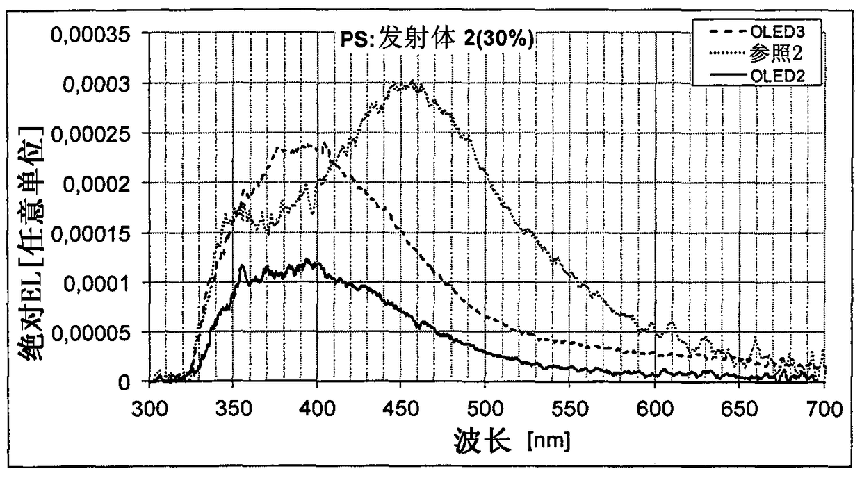
[0135] The following two emitters E1 and E2 are used.
[0136]
[0137] The synthesis of E1 is disclosed in EP 329752 and the synthesis of E2 in EP 440082.
[0138] The host used was polystyrene (PS) from Fluka (81414, Mw 500000, Mn 490000). BM1 and BM2 are ZrO x and HfO x precursor material (x≤2). The synthesis of the precursors was performed according to WO 2010 / 078907.
Embodiment 2
[0140] Solutions and compositions comprising matrix material and emitter
[0141] Solutions as outlined in Table 1 were prepared as follows: First, the host and emitter mixture was dissolved in 10 ml toluene and stirred until the solution was clear. The solution was filtered using a Millipore Millex LS hydrophobic PTFE 5.0 μm filter.
[0142] Table 1:
[0143]
[0144] These solutions are used to make the emissive layers of OLEDs. The corresponding solid compositions can be obtained by evaporating the solvent from the solutions. This can be used to prepare additional formulations.
Embodiment 3
[0146] Fabrication of organic electroluminescent devices
[0147] OLED Reference 1 and Reference 2 have the following structure: ITO / PEDOT / EML / cathode. These two OLEDs were used as reference examples. They were produced according to the following steps using the corresponding solutions from Table 1:
[0148] 1. 80nm PEDOT (Clevios TM P VP AI 4083) was applied to an ITO-coated glass substrate. It was then dried by heating at 120° C. for 10 minutes in a clean room.
[0149] 2. Apply a 100 nm emissive layer by spin coating the solutions according to Table 1 in an Ar glove box.
[0150] 3. Dry the device by heating at 180°C for 10 minutes.
[0151] 4. Apply Ba / Al cathode (3nm+150nm) by vapor deposition.
[0152] 5. Package the device.
[0153]OLED1-OLED3 are devices according to the invention having the following structure: ITO / BL / EML / cathode, where BL stands for exciton blocking layer. They were produced using the solutions from Table 1 by the method described for OLED-Re...
PUM
 Abstract
Description
Claims
Application Information
 - R&D
- Intellectual Property
- Life Sciences
- Materials
- Tech Scout
- Unparalleled Data Quality
- Higher Quality Content
- 60% Fewer Hallucinations
Browse by: Latest US Patents, China's latest patents, Technical Efficacy Thesaurus, Application Domain, Technology Topic, Popular Technical Reports.
© 2025 PatSnap. All rights reserved.Legal|Privacy policy|Modern Slavery Act Transparency Statement|Sitemap|About US| Contact US: help@patsnap.com


