Bladder pressure detecting device and method for analyzing opportunity of patient for removing catheter

A detection device and pressure technology, applied in catheters, balloon catheters, diagnostic recording/measurement, etc., can solve problems such as pressure sensor contamination, expensive urodynamic testing equipment, and patient infection

Inactive Publication Date: 2015-08-26
CHI MEI MEDICAL CENT
View PDF8 Cites 6 Cited by
  • Summary
  • Abstract
  • Description
  • Claims
  • Application Information

AI Technical Summary

Problems solved by technology

In terms of use, since the catheter is inserted into the patient's body and cannot move by himself, the medical staff must push the urodynamic testing equipment to the side of the patient for testing, but the general urodynamic testing equipment is usually bulky and difficult to carry , causing troubles in use; and urodynamic testing equipment is expensive, and it is not easy to popularize testing in hospitals
[0003] In addition, a pressure sensor is combined with a urinary catheter to sense bladder pressure, such as Chinese patent CN102579029, but in this case, the pressure sensor is set on the flow path of urine, and the pressure sensor is a mechanical component. If the pressure sensor is not sterilized, it is completely possible cause infection
And the pressure sensor is set on the flow path of urine, which will also cause the pressure sensor to be contaminated by urine. In order to avoid cross-infection of patients, the pressure sensor cannot be reused
[0004] In view of this, the inventor of the present invention aimed at many shortcomings and inconveniences caused by the imperfect structural design of the above-mentioned bladder pressure detection device.

Method used


Image

  • Bladder pressure detecting device and method for analyzing opportunity of patient for removing catheter
  • Bladder pressure detecting device and method for analyzing opportunity of patient for removing catheter
  • Bladder pressure detecting device and method for analyzing opportunity of patient for removing catheter

Examples


Embodiment Construction

[0038] In order to further explain the technical solution of the present invention, the present invention will be described in detail below through specific examples.

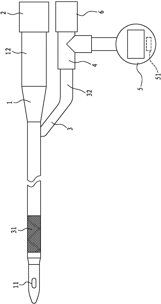
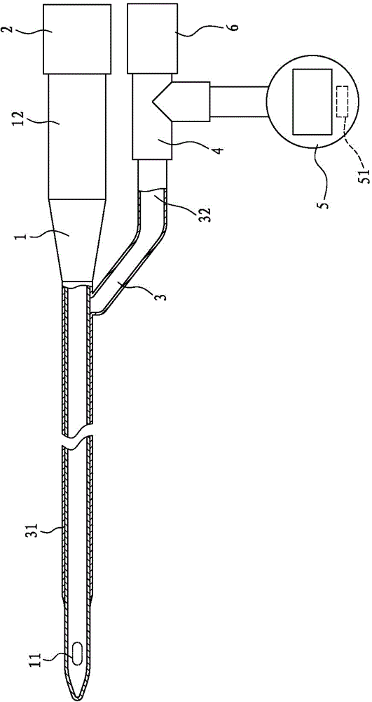
[0039] see figure 1 and figure 2 As shown, the bladder pressure detection device in the first preferred embodiment of the present invention combines the functions of a traditional urinary catheter, including:

[0040] A first tube body 1, the opposite ends are hollow, including a catheterization end 11 and a urination end 12, and a valve 2 is arranged on the urination end 12 of the first tube body 1; a second tube body 3, Sleeved outside the first pipe body 1, the second pipe body 3 has an expansion end 31 and a pressure detection end 32 connected to the expansion end 31, and the expansion end 31 is connected to the first pipe body 1 to form a closed type state and close to the catheter end 11, one end of a three-way pipe 4 is connected to the pressure detection end 32 of the second pipe body 3, one end is c...


PUM


Abstract

The invention discloses a bladder pressure detecting device and a method for analyzing the opportunity of a patient for removing a catheter. The bladder pressure detecting device comprises a catheter body and a pressure gage, wherein the catheter body has an expanding end and a pressure detecting end communicated with the expanding end, and the expanding end is closed; and the pressure gage is communicated with the pressure detecting end of the catheter body. The method for analyzing the opportunity of the patient for removing the catheter includes the steps that the catheter body extends into the bladder of the patient so that the expanding end can bear the pressure of extrusion of urine in the bladder or the pressure of contraction of the bladder, and then the pressure value is measured through the pressure gage; and when the bladder pressure detecting device and the catheter are integrated together, the bladder pressure detecting device can be used for analyzing the urination condition of the patient or the shrinkage force application condition of the detrusor of the bladder of the patient through the pressure value when the catheter is inserted into the body of the patient, and whether the catheter needs to be removed or not can be judged through the bladder pressure detecting device.

Description

technical field [0001] The invention relates to a bladder pressure detection device and a method for analyzing the timing of patient removal of a urinary catheter, in particular, one end of a tube body is inserted into the bladder to withstand the pressure in the bladder, and the pressure is detected at the other end of the tube body for Devices and methods for utilization / interpretation. Background technique [0002] At present, there is an improved catheter structure, combined with urodynamic examination equipment, in addition to the general urodynamic examination of the patient, it can also be used to detect the internal bladder pressure and urination capacity of the patient to assist doctors in judgment Whether the urinary catheter can be removed. In terms of use, since the catheter is inserted into the patient's body and cannot move by himself, the medical staff must push the urodynamic testing equipment to the side of the patient for testing, but the general urodynami...

Claims


Application Information

Patent Timeline
Patent Type & Authority Applications(China)
IPC IPC(8): A61B5/03A61M25/10
CPCA61M25/10A61B5/03A61B5/036A61B5/6852A61B5/205A61M25/04A61M25/0017
Inventor 王志中黄冠华林伯昰林俊宏
Owner CHI MEI MEDICAL CENT
Why Eureka
Try Eureka