Elastic wave mode separation method and elastic wave mode separation system
A technology of mode separation and mode separator, applied in the direction of fluid using vibration
- Summary
- Abstract
- Description
- Claims
- Application Information
AI Technical Summary
Problems solved by technology
Method used
Image
Examples
Embodiment 1
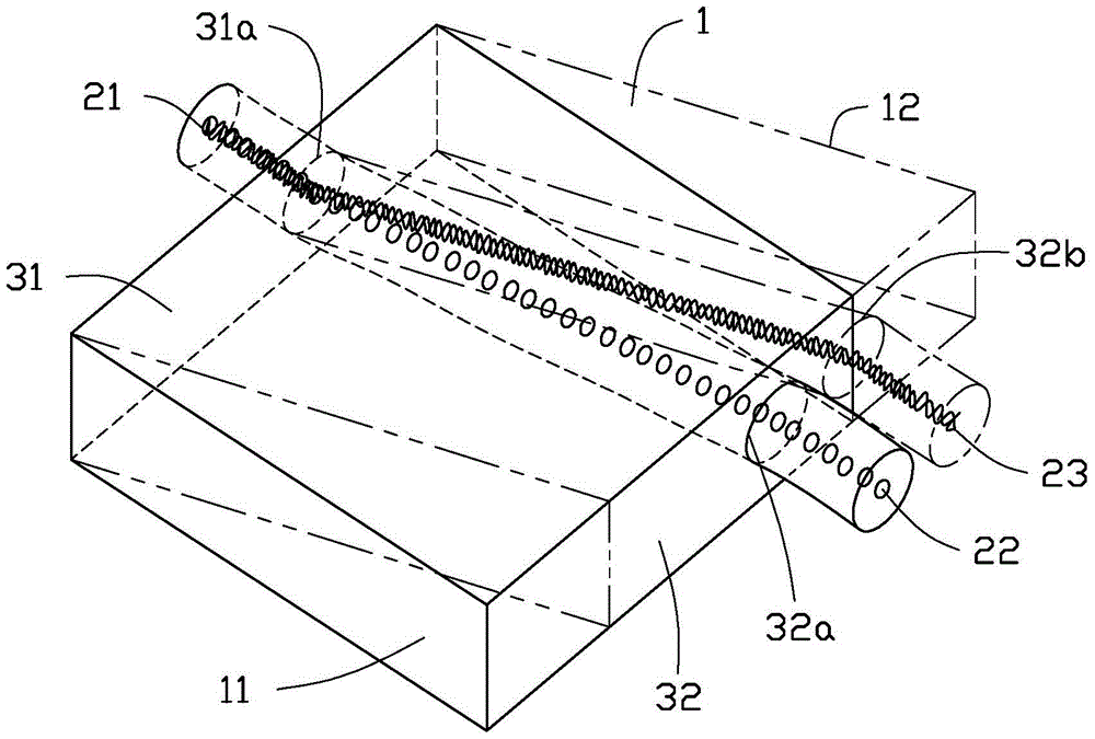
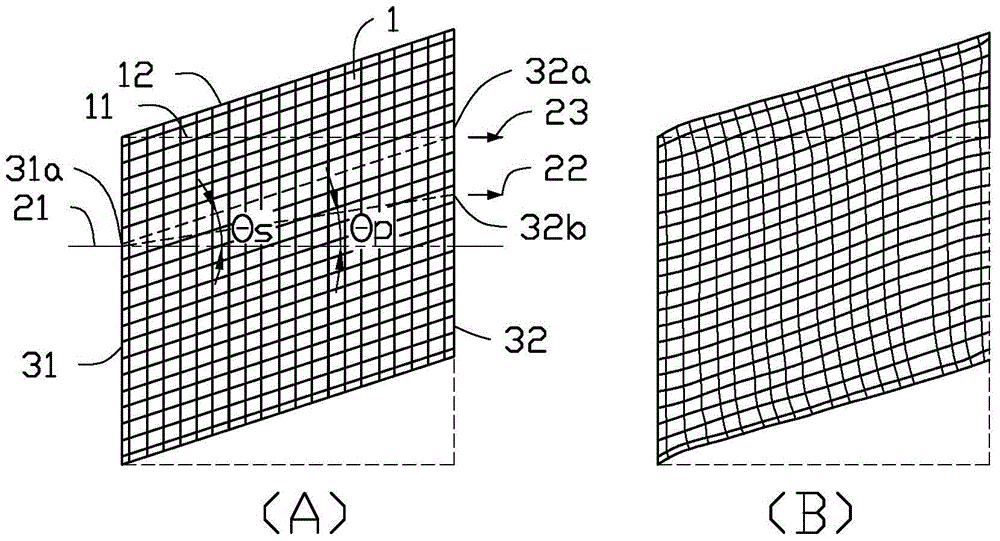
[0072] As an embodiment of the present invention, the New Hooke material 1 is selected to be approximately incompressible, and the material produces uniform and simple shear deformation under the action of body displacement load. For this reason, in the case of plane strain, the new Hooke material PSM-4 with a square section of 12cm×12cm (material parameter λ = 2GP, aμ = 1.08MPa and the initial state bulk density ρ = 1050Kg / m 3 ) Applied body displacement load U y =-(x-0.6) / 30m (unit: m, that is, apply the corresponding displacement load U at all points of the corresponding coordinate x of the new Hook material 1 y ) To produce uniform and simple shear deformation of the material, the corresponding deformation gradient tensor is as (2), and tanγ=1 / 3. Such as Figure 7 As shown in a, the body coordinate line of the material is evenly distributed. At the same time, calculate the von-Mises stress of the material to be 6.35×10 5 N / m 2 , Which shows that the material presents a unifo...
Embodiment 2
[0074] As another embodiment of the present invention, the New Hooke material 1 is selected to be compressible, and the material produces uniform and simple shear deformation under the action of body displacement load. For this reason, the material parameters of New Hooke material 1 are selected as λ=4.32MPa, μ=1.08MPa and ρ=1050Kg / m 3 . The position where the elastic wave excitation is applied and the corresponding displacement amplitude are the same as those in the first embodiment, but the angular frequencies of the P wave and the S wave in this example are both set to ω=0.3MHz. The demultiplexing effect of the device is similar to the previous embodiment, such as Figure 7 Shown in d. Similarly, the N at the vertical line segment 33 in this example P And N S The spatial distribution of Figure 7 As shown in e. The difference from the previous example is that in addition to the change in the propagation path of the S wave, the propagation path of the P wave has also undergo...
Embodiment 3
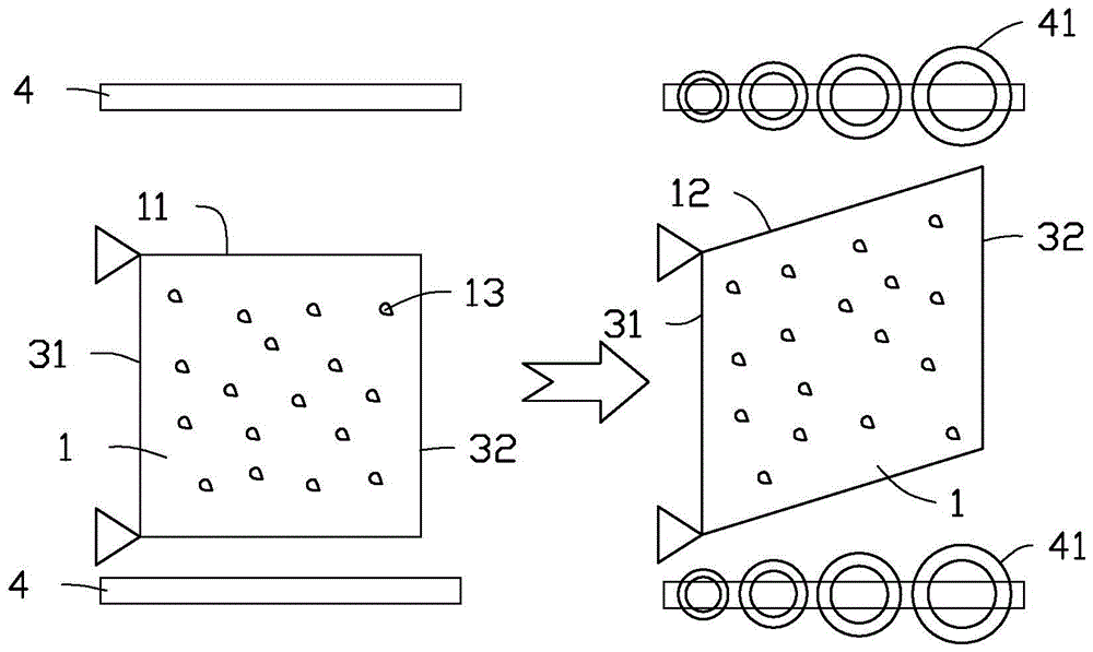
[0080] As another embodiment of the present invention, the New Hooke material 1 is selected to be approximately incompressible, and at the same time, the material is similar to that under the action of boundary displacement load. figure 2 The approximate simple shear deformation of b. For this reason, in the case of plane strain, the first surface 31 of the new Hooke material PSM-4 (the material parameters are the same as above) with a square section of 12cm×12cm is fixed, and a displacement load U is applied to the second surface 32 y =4cm, which makes the New Hooke material 1 produce approximately simple shear deformation, the deformation gradient tensor is approximately as (2), and tanγ=1 / 3. The other experimental parameters and characterization methods of this embodiment are the same as those of embodiment 1. The experimental results are as Picture 9 Shown in a-c. It can be seen that the approximate simple shear deformation causes the P wave and S wave propagating in the ...
PUM
 Abstract
Description
Claims
Application Information
 - R&D
- Intellectual Property
- Life Sciences
- Materials
- Tech Scout
- Unparalleled Data Quality
- Higher Quality Content
- 60% Fewer Hallucinations
Browse by: Latest US Patents, China's latest patents, Technical Efficacy Thesaurus, Application Domain, Technology Topic, Popular Technical Reports.
© 2025 PatSnap. All rights reserved.Legal|Privacy policy|Modern Slavery Act Transparency Statement|Sitemap|About US| Contact US: help@patsnap.com


