
Fixture for Automatic Positioning of Axial Holes of Shaft Parts

A technology for automatic positioning and shaft parts, applied in positioning devices, metal processing machinery parts, clamping, etc., can solve problems such as easy loosening and difficult positioning of bolts, and achieve the effects of improving quality, eliminating front-end vibration, and improving processing accuracy

Active Publication Date: 2017-05-03
ANHUI HELI CO LTD
View PDF6 Cites 0 Cited by
  • Summary
  • Abstract
  • Description
  • Claims
  • Application Information

AI Technical Summary

Problems solved by technology

[0004] In order to solve the defects of the existing V-shaped block support and positioning device, such as difficult pin positioning and easy loosening, the present invention designs a fixture for automatic positioning of the axial hole of shaft parts

Method used


Image

  • Fixture for Automatic Positioning of Axial Holes of Shaft Parts
  • Fixture for Automatic Positioning of Axial Holes of Shaft Parts
  • Fixture for Automatic Positioning of Axial Holes of Shaft Parts

Examples


Embodiment Construction

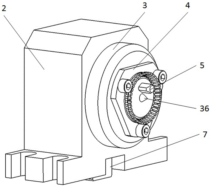
[0035] see figure 1 , a fixture for automatic positioning of axial holes of shaft parts, including a front positioning clamping mechanism, a tail clamping mechanism, more than one middle V-shaped block 6 and a bottom plate 1;

[0036] The bottom plate 1 is a rectangular plate, the middle part of which is provided with a positioning groove 12 along the length direction; the front positioning clamping mechanism and the tail clamping mechanism are respectively fixed at the two ends of the bottom plate 1 in the length direction, and more than one middle V-shaped block 6 is fixed on the middle part of the bottom plate 1;

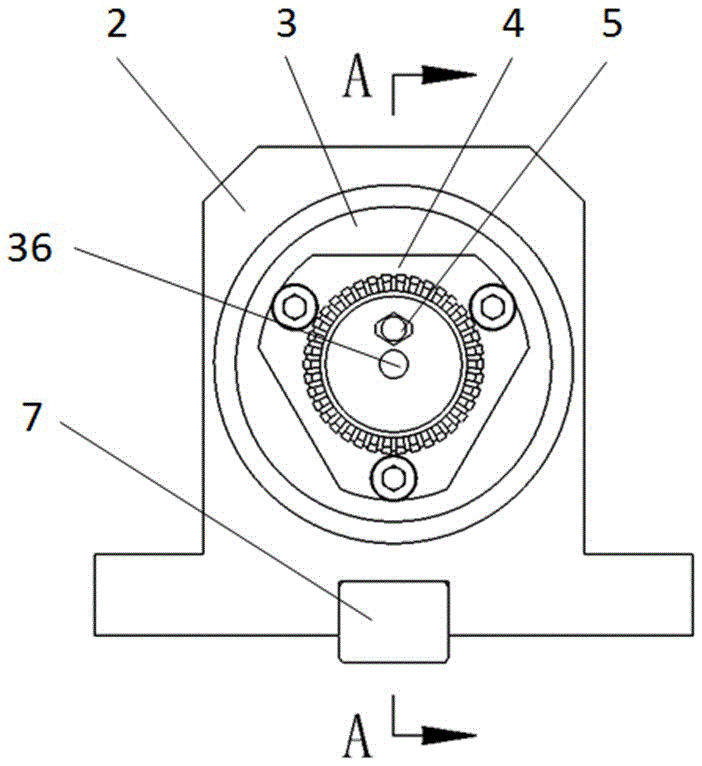
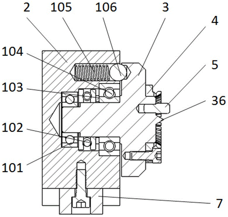
[0037] The front positioning clamping mechanism includes a baffle plate 2, a baffle plate thimble 3 and a bushing 4;

[0038] see Figure 5 , the baffle plate 2 is in the shape of a rectangular block, the middle part of the inner end surface is horizontally recessed with a rotary hole 23, the rotary hole 23 is a stepped hole, the top of the inner end surface is...


PUM


Abstract

A fixture for shaft part axial hole automatic positioning comprises a front positioning and clamping mechanism, a tail ejecting mechanism and a bottom plate. The bottom plate is a rectangular plate, and the front positioning and clamping mechanism and the tail ejecting mechanism are fixed to the two ends of the bottom plate; the front positioning and clamping mechanism comprises a baffle, a baffle ejector pin and a bush; a rotary hole is formed in the middle of the baffle, the top of the baffle is provided with a positioning hole, and a spring is arranged in the positioning hole; a rotary shaft at one end of the baffle ejector pin is matched with the interior of the rotary hole, and more than three ball holes are distributed in the circumference of the end face of a round plate at the other end of the baffle ejector pin; a positioning ball is arranged at the outer end of a spring in the positioning hole, and part of a ball body of the positioning ball extends into one of the more than three ball holes; the other end face of the round plate is provided with a pin hole and a centre; the bush is fixed to the round plate through a fixing plate, and an annular elastomer is arranged on the edge of the round hole; the tail ejecting mechanism comprises a tailstock base, a tailstock ejector pin and a handle; the tailstock ejector pin is arranged in the middle of the tailstock base, a screw rod is arranged at the outer end of the tailstock ejector pin, and the extending end of the screw rod is connected with a rotary handle in a matched mode.

Description

technical field [0001] The invention belongs to the field of mechanical processing tooling, in particular to a fixture for automatic positioning of axial holes of shaft parts. Background technique [0002] The machining of small radial holes in shaft parts has always been difficult, especially for several rows of holes in the axial direction, which need to penetrate the axial holes and radial holes, making clamping and positioning difficult. V-shaped block support and positioning device is usually used now. The front end is limited by the end face of the baffle, and the rear end is firmly supported by a thimble. pin positioning; [0003] The existing positioning device has the following problems: (1), the front end of the workpiece only relies on the friction between the end surface of the workpiece and the front baffle to constrain the workpiece, and then supports the workpiece with a V-shaped block, which cannot be fixed only by the friction between the front baffle and t...

Claims


Application Information

Patent Timeline
Patent Type & Authority Patents(China)
IPC IPC(8): B23Q3/06B23Q7/00
CPCB23Q3/062B23Q7/00
Inventor 袁兵昌郑吉先朱晓敏张琴
Owner ANHUI HELI CO LTD
Learn More