Disc cutting device

A technology for cutting devices and discs, applied in printing devices, printing, etc., can solve the problems of waste of cutting processing time, large movement of the circular knife, etc.

Inactive Publication Date: 2015-08-26
TOSHIBA TEC KK
View PDF4 Cites 7 Cited by
  • Summary
  • Abstract
  • Description
  • Claims
  • Application Information

AI Technical Summary

Problems solved by technology

Therefore, there is no problem when the width of the medium is close to the cuttable width of the circular knife portion, but when the width of the medium used is half of the cuttable w

Method used


Image

  • Disc cutting device
  • Disc cutting device
  • Disc cutting device

Examples


Embodiment Construction

[0023] Next, the disk cutting device according to this embodiment will be described in detail with reference to the drawings. In addition, the embodiment described below is only an example of this invention, As long as the structure of each part can achieve the object of this invention, it cannot be overemphasized that it can change or amend suitably within the range.

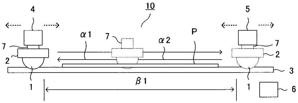
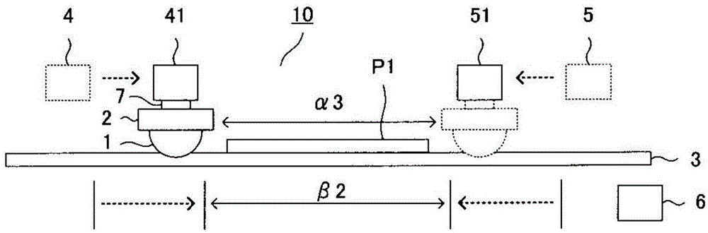
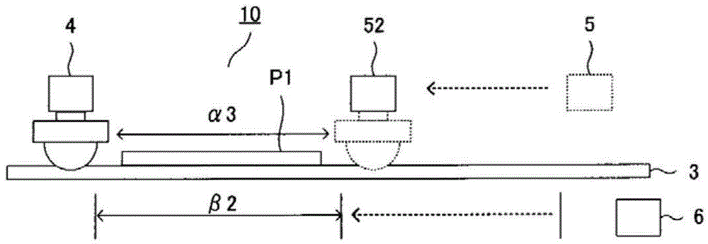
[0024] figure 1 is a schematic configuration diagram of a disk cutting device according to this embodiment, figure 2 Yes means applicable to figure 1 Diagram of the disc cutting device in the case of narrow-width media P1, image 3 is to indicate that the figure 2 The diagram of the disc cutting device in which the printing reference in is set to one side.

[0025] The disc cutting device (disc cutter device) related to this embodiment is used in thermal duplication and thermal printers having a thermal head for printing labels or price tag A device that cuts the medium P into a specified length.

[002...


PUM


Abstract

The present invention discloses a disc cutting device which can be consistent with the width of a medium to carry out the cutting processing effectively. The disc cutting device comprises a fixing knife arranged in the width direction of the medium; a circular knife moving along the fixing knife, and cutting the above medium with the above fixing knife cooperatively; a first standby position sensor and a second standby position sensor which can move in the above width direction, and are configured at one side and the other side of the outer side of the width (breadth) of the above medium; a detection board detected by the above first and second standby position sensors; and a circular knife part rotating freely to support the above circular knife, possessing the above detection board, and moving between the above first and second standby position sensors.

Description

technical field [0001] The present invention relates to a disc cutting device, in particular to a disc cutting device for cutting media used in thermal duplication and thermal printers into predetermined lengths. Background technique [0002] In recent years, a disk cutting device cuts a conveyed medium by moving a circular blade portion having a circular blade in a direction perpendicular to the conveyance direction of the medium. From the perspective of the conveying direction, the position control of the circular knife part is carried out by the standby position sensors arranged at both ends. The circular knife part on standby at one end moves to the detection position of the standby position sensor at the other end to cut the medium, and the next Standby at the detection position of the standby position sensor at the other end before a cutting action. [0003] In such a disk cutting device, such as in thermal duplication and thermal printers with a thermal head, the amo...

Claims


Application Information

Patent Timeline
IPC IPC(8): B41J11/70
Inventor 吉越和幸
Owner TOSHIBA TEC KK
Why Eureka
Try Eureka