Timing signal fault diagnosis device for electronic control internal combustion engine

An internal combustion engine, engine technology, applied in the direction of internal combustion piston engine, combustion engine, engine control, etc., can solve problems such as lack of availability and inability of the engine to run

Active Publication Date: 2015-08-26
INJECTRONIX CO LTD
View PDF5 Cites 7 Cited by
  • Summary
  • Abstract
  • Description
  • Claims
  • Application Information

AI Technical Summary

Problems solved by technology

Failure of the two timing signals will directly cause the engine to fail to run
For most maintenance practitioners, they do not have the technical skills to use a general-purpose oscilloscope, so they can only disassemble the relevant parts to troubleshoot based on experience

Method used


Image

  • Timing signal fault diagnosis device for electronic control internal combustion engine
  • Timing signal fault diagnosis device for electronic control internal combustion engine
  • Timing signal fault diagnosis device for electronic control internal combustion engine

Examples


Embodiment Construction

[0050] Timing Signal Failure Detection Mode

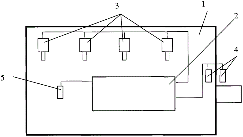
[0051] An EFI engine 1 can still run. The ECU fault code indicates a failure of one timing signal.

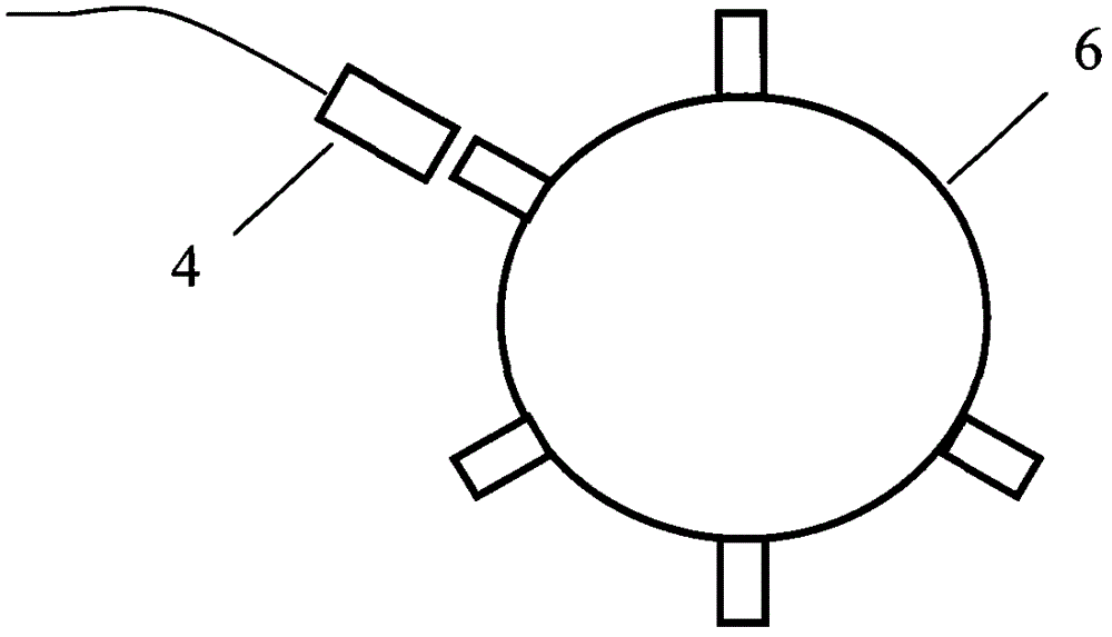
[0052] Connect two timing sensors 4 of engine, engine ECU2 and two timing signal input terminals 14 of the present invention with two three-way cables. Like this engine ECU2 and the present invention 9 can detect the signal of 2 road timing sensors 4 simultaneously.

[0053] Select the model of the engine to be tested through the user interface 13 . The central processing unit 11 reads in the corresponding timing signal characteristic parameters in the database 12 .

[0054] Start the engine, steady at idle. The start of detection of the timing signal is instructed through the user interface 13 .

[0055] The input timing signal 14 becomes a square wave signal through the shaping circuit 16, and the identification input timing signal module 17 identifies the two-way timing square-wave signal to generate two time sequences bas...


PUM


Abstract

A timing signal fault diagnosis device for an electronic control internal combustion engine comprises a central processing unit 11, a timing signal processor 10, a database memory 12, a user interface 13, timing signal input interfaces 14 and timing signal output interfaces 15. According to the device, three working modes are provided, and an input timing signal format is analyzed and compared with a pre-stored format in the database memory 12 to realize the timing signal fault diagnosis; a timing signal input into a novel engine is analyzed, and the characteristic parameter of the timing signal is stored in the database memory 12 for diagnosis of the fault of the same model of engine in the future; the timing signal is output, an ECU (electronic control unit) is activated, and accordingly, fault diagnosis for an engine which cannot operate is facilitated.

Description

technical field [0001] The invention relates to a fault diagnosis device for electronically controlling the timing signal of an internal combustion engine. Background technique [0002] Electronic control technology (referred to as electronic control) is widely used in modern internal combustion engines. attached figure 1 Shown is a typical electronically controlled internal combustion engine. figure 1 1 in is the electronically controlled engine. 2 is the control computer ECU. 3 is an electronically controlled actuator, such as an electromagnetic actuator equipped on an electronically controlled fuel injector, an electronically controlled fuel injection pump, and the like. 5 is a sensor for detecting physical quantities such as engine pressure and temperature. 4 is the engine synchronous speed sensor, also known as the timing sensor. The sensor is installed at a very close position on the periphery of the toothed disc that rotates at the rotational speed of the cranks...

Claims


Application Information

Patent Timeline
Patent Type & Authority Applications(China)
IPC IPC(8): F02D41/22
CPCY02T10/40
Inventor 姜禾
Owner INJECTRONIX CO LTD
Why Eureka
Try Eureka